Hierarchy Design – Part 2
Last Updated: [last-modified] (UTC)
In part 1 of this article, we looked at the different topologies of the hierarchical design.
In part 2, we’ll look at some of the principles and best practices to use when designing one of these networks.
If you haven’t read part 1 yet, head over there first, then come back here when you’re ready
[maxbutton id=”4″ text=”Hierarchical Design Part 1″ url=”https://networkdirection.net/Hierarchy+Design+Part+1″]
Design Principles
Access Layer
Keep the design simple and flexible where possible. One way to do this is to use the same config on all host-facing ports. Any host port can support workstations, printers, phones, and other devices.
This does not mean that every port is a trunk. Configure them as access ports, with an access VLAN and a voice VLAN. The switchport host macro can simplify this. The AccessEdgeQoS macro is also useful for packet marking.
Avoiding custom port config improves modularity, making it easy to deploy new switches. This is also simpler to troubleshoot, as you already know the configuration of every port.
 Keep management simple and secure. Disable insecure management protocols (telnet and HTTP). Use only the secure alternatives (SSH and HTTPS).
For logins, use AAA services with RADIUS or TACACS. This means that users don’t have to exist on each switch. Have a small number of local user names configured, and the passwords encrypted. This is so the switch can fall back to local authentication if the RADIUS or TACACS server were to fail.
To connect to the switch, use in-band management. This means creating a management VLAN with an SVI.
For logging, enable NTP so the timestamps are accurate. Also consider using a common timezone across all sites. This makes it easier to compare log timestamps between different devices.
When thinking about the switch platform to use in the access layer, think about:
- Budget. This includes the initial cost (CapEx) and the ongoing cost (OpEx) for support contracts
- Licenses. What features do we need? What’s supported out of the box?
- Port density. Make sure that you will have enough ports, and plan for growth
- Failover times. Does this switch support the protocols you need for fast convergence?
- Stacking. Is stacking required for HA?
- Features. Are all the features I need available on this platform?
Core and Distribution Layers
 Many of the access layer principles also apply to the core and distribution layers. There are a few unique approaches to take with these layers.
For management, use loopback’s rather than SVI’s. The reason is that these layers run at layer 3.
The distribution layer protects the core from problems occuring in the access layer. This includes route summarization, to keep the core routing table lean.
Some deployments will use a First Hop Routing Protocol (FHRP). If this is the case, it in the distribution layer.
Before designing the core, decide if a dedicated core layer is even needed. Can we combine the core and distribution layers in a collapsed core model?
When you do have a dedicated core, get the configuration right, and then leave it. This layer needs to be ‘always-up’, and the more you fiddle with it, the higher the risk of outage. The same goes for the code that runs on the core switches. Select a well-known stable version, and leave it there. Don’t upgrade it unless it’s necessary.
Campus Mobility
 Devices move throughout the network. This includes tablets, phones, laptops, and so on. This is common in wireless networks, but don’t forget to consider wired mobility as well.
One simple aspect to this is having DHCP servers available to hand out addresses to mobile hosts. Another is using CDP or LLDP so phones can get PoE and QoS settings as required. This applies to mobility, as well as deploying new endpoints.
When devices move, it’s important that the appropriate policies are still applied. This includes identification and authentication, QoS policies, and edge security policies. One solution to these challenges is to use a combination of identity services and 802.1X.
Control and Data Plane
It is important to understand how the control and data plane work in the environment.
FHRP’s impact both the data plane and control plane. When it handles MAC addresses in response to an ARP request, this is control plane traffic. Forwarding traffic is data plane traffic.
For more information, see the Control and Data Plane article
[maxbutton id=”4″ text=”Control and Data Plane” url=”https://networkdirection.net/Control+and+Data+Plane”]
When designing the network, try to get the control and data plane to match. To do this, match these three components:
- Physical topology
- Logical control plane
- Data flows
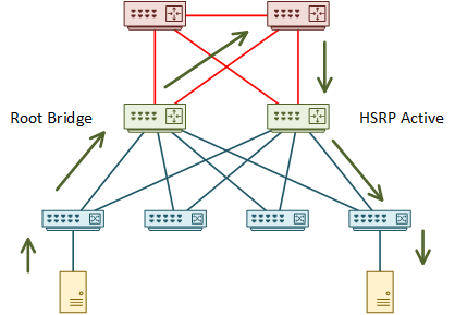
An example in practice is mixing HSRP and spanning-tree. Start by considering the example below.
In this network, one of the distribution switches is the root bridge. The root bridge draws traffic toward itself. The other distribution switch is the active HSRP member.
Think about one host sending traffic to another. The root bridge pulls traffic toward itself. It then takes a sub-optimal path through the core to the active HSRP member. The traffic is finally forwarded to the recipient.

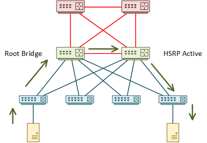
There are a few problems with this. The physical topology isn’t suitable, resulting in the suboptimal path through the core. Address this by adding a link between the distribution switches.

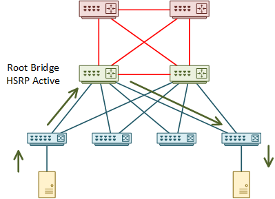
Even after this change, the topology is still not optimal. This is because the root bridge and the active HSRP member are on different switches. Adjust either of these to make one switch handle both functions.

When thinking this design through, think deterministically. Think about what would happen if there were a failure. Which alternate paths would the switch choose? Are they optimal, or is there a way to improve them?
Also consider what would happen after repairing a failure. Imagine if the second switch became active again due to a failure on the first switch. What happens after repairing the first switch? Is HSRP preemption enabled, or will the path be sub-optimal?
Bandwidth and Over-Subscription
 It is reasonable to over-subscribe bandwidth between the layers. This assumes that not all devices are sending traffic at their greatest capacity at one time.
Generally, bandwidth between access and distribution can be over-subscribed at 20:1. Bandwidth between the distribution and core layers may be over-subscribed up to 4:1.
Consider that, depending on the topology, some links may not be active. When working out your bandwidth ratios, consider active links only.
So, if you have an access layer switch with 48 1Gbps ports, it has a bandwidth of 48Gbps. This assumes that the switch’s backplane can handle it. At a ratio of 20:1, the uplinks to the distribution layer will need to have at least 2.4Gbps of active bandwidth.
Now think about link failure. In the example above, three 1Gbps uplinks would meet the requirements. If one link fails, the uplink bandwidth would drop to 2Gbps, which is below the recommended value. In this case, four uplinks would be a better design.
This can get more confusing when wireless access points enter the picture. In this case, it’s not as simple as counting the physical ports like you would with a switch. A best estimate is a good place to start, but in the long run, monitoring the solution will be critical.
If bandwith needs to be upgraded, there are a few options:
- Replace the existing links with larger links
- Add links to an etherchannel
- Add more ECMP links
There is a hidden catch when adding links to etherchannels. More links means more bandwidth, which means that the cost of the link changes. This also applies when removing links from etherchannels.
Depending on topology, this could cause the IGP to reconverge, or to change ECMP paths. OSPF is sensitive to the ECMP issue, as it doesn’t use unequal cost load balancing by default.
To work around this, consider enabling unequal-cost load balancing, or statically defined costs.
EIGRP isn’t affected by the ECMP issue as much, as it supports unequal paths by default. Also, EIGRP looks at metrics end-to-end (it looks for bottle necks), while OSPF uses a cumulative cost. If the recalculation doesn’t affect the end-to-end metric, the ECMP paths shouldn’t change.
Adding more routed links makes use of ECMP routing. This refers to a case where each link is routed, rather than being in a routed etherchannel.
This is generally easier to tune and troubleshoot than etherchannel. It’s easy to find a failed neighbour relationship, and easy to find an individual failed link. This is the recommended option in most cases.
CEF distributes traffic across ECMP paths. Like etherchannel, this uses a hashing algorithm to decide which flows are on each link. By default, the algorithm uses source and destination IP addresses. This is tunable.
When tuning CEF, be careful to avoid CEF Polarization. This is where traffic gets pinned to particular links all the way through the layers. This leaves other links unused.
A particular hashing algorithm may work well between core and distribution. Don’t assume that it’s also the right choice for the distribution to access layer. Do your own monitoring, and take actions based on what is best for your network.
References
Cisco Live – BRKCRS-1500 – Campus Wired LAN Deployment Using Cisco Validated Designs
Cisco Live – BRKCRS-2031 – Enterprise Campus Design: Multilayer Architectures and Design Principles
Cisco – Enterprise Campus 3.0 Architecture: Overview and Framework
Marwan Al-shawi and Andre Laurent – Designing for Cisco Network Service Architectures (ARCH) Foundation Learning Guide: CCDP ARCH 300-320 (ISBN 158714462X)