
Advanced vPC
Introduction
Before reading this article, please read the Virtual Port Channel article.
In the following sections we will dig deeper into the inner workings of vPC, covering topics such as:
- Duplicate frame control
- The vPC Control Plane
- Primary and Secondary Roles
- Domain/System ID’s and LACP
- Auto-recovery
Duplicate Frame Control
There is one critical rule with vPC. If a member port receives a frame, it is forwarded across the peer-link. When the peer switch receives it, it will not forward the frame out a vPC member port. Why does this happen? Have a look at the diagram below.
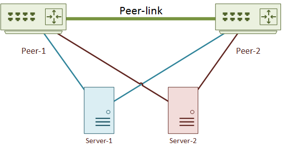
Frames received on a member port, then forwarded across the peer-link, will not be forwarded out another member port
There are two servers connected by vPC member ports. Server-1 sends a frame to Server-2. The traffic flows like this:
- The frame travels up the link from Server-1 to Peer-1
- Peer-1 forwards the frame down the link to Server-2
- Peer-1 also forwards the frame across the peer-link to Peer-2
- Peer-2 sees that the frame came from a vPC member port, and refuses to forward it to Server-2
So, why does Peer-2 drop the frame? Peer-1 has already delivered it. If Peer-2 also tried to deliver the frame, server-2 would receive a duplicate frame.
Of course, this does not apply to orphaned ports. They are not multi-homed with vPC, and cannot get duplicate frames.
Control Plane
The control plane, roughly defined, is when traffic sent to a switch. This is different to the data plane, when switches forward traffic. An example of control plane traffic is a spanning-tree BPDU. An example of data plane traffic is when one host sends traffic to another host.
Each switch has its own control plane. When two switches are in a vPC domain, they appear to other devices to have a single control plane. The System ID and the vPC roles achieve this.
Primary and Secondary Roles
One vPC peer holds the primary role, and the other holds the secondary. By default, only the primary switch responds to control plane traffic. For example, when traffic such as an ARP request is sent to the domain, the primary switch responds. This is one way that the vPC pair appears to be a single control plane to connected devices.
The roles are decided upon based on the priority. The lower the value, the higher the priority. The initial election happens when switches join the vPC domain. When the primary switch reloads, its peer assumes the primary role. When the switch finishes reloading, it will continue to hold the secondary role. vPC is non-preemptive to prevent control plane disruptions caused by unnecessary role changes.
Failover
Some platforms and versions do support role failover. See the Hitless vPC Role Change blog post for more information.
Check which role the switch currently holds with show vpc brief. In the example below, the switch has been configured as primary, but is acting as secondary. This is presumably due to some past failure.
Switch-1# show vpc brief
Legend:
                (*) - local vPC is down, forwarding via vPC peer-link

vPC domain id                     : 10
Peer status                       : peer adjacency formed ok
vPC keep-alive status             : peer is alive
Configuration consistency status  : success
Per-vlan consistency status       : success
Type-2 consistency status         : success
vPC role                          : primary, operational secondary     ! --This switch is configured as primary, but has the secondary role--
Number of vPCs configured         : 0
Peer Gateway                      : Disabled
Dual-active excluded VLANs        : -
Graceful Consistency Check        : Enabled
Auto-recovery status              : Disabled
Delay-restore status              : Timer is off.(timeout = 30s)
Delay-restore SVI status          : Timer is off.(timeout = 10s)
Operational Layer3 Peer-router    : Disabled
Domain ID, System ID, and LACP
vPC still uses LACP. The devices that connect to vPC use normal etherchannels or LAGs. They need to negotiate their parameters with LACP. The LACP standard needs all connections in a LAG to be between two devices only. Connecting to more than one device at a time is an error as far as LACP is concerned.
When creating a port channel, LACP does its due diligence and compares a few values. The first is the System ID. This is a unique value on each switch. It is a 64-bit value which can be manually assigned or automatically generated. Auto assignment comes from the system priority and the System MAC address. The second value is an identifier for the LAG, such as the port-channel ID.
These four values (two at each end) create a LAGID (Link Aggregation Group Identifier). All ports in a port-channel must have the same LAGID. If there is a mismatch, the ports are excluded or the LAG stays down, depending on the implementation.
But vPC uses two switches at one end of the link. This would cause havoc for LACP, as there would be two different LAGIDs. vPC is crafty and gets around this problem. It does this by generating the System ID from the system MAC. The system-MAC is generated from the Domain ID and a pool of virtual MAC addresses.
These values match on both peers, so there is a single System ID as far as LACP is concerned. LACP will see the switch pair as a single device.
See the System-MAC with the show vpc role command.
Switch-1# show vpc role

vPC Role status
----------------------------------------------------
vPC role                        : primary
Dual Active Detection Status    : 0
vPC system-mac                  : 00:23:04:ee:be:0a     ! 0a is 10 in hexadecimal, the domain ID
vPC system-priority             : 32667
vPC local system-mac            : 28:6f:7f:7d:e3:f7
vPC local role-priority         : 10
When LACP is used, it is recommended that the System Priority be manually configured. This is so the vPC switch pair will always be the LACP primary devices. It is critical that these values match on both switches, or the vPC will not come up.
Switch-1(config)# vpc domain 10
Switch-1(config-vpc-domain)# system-priority 1000

Switch-1# show vpc role

vPC Role status
----------------------------------------------------
vPC role                        : primary
Dual Active Detection Status    : 0
vPC system-mac                  : 00:23:04:ee:be:0a
vPC system-priority             : 1000
vPC local system-mac            : 28:6f:7f:0a:fd:95
vPC local role-priority         : 10
M1NX01#
The Domain ID should be different on each pair of vPC switches, to avoid System ID conflicts. There may be a rare case where the Domain ID’s must be the same. If needed, change the System ID by changing the System MAC, as shown below.
vpc domain 10
  system-mac 0023.04ee.be11
  exit

show vpc role

vPC Role status
----------------------------------------------------
vPC role                        : primary
Dual Active Detection Status    : 0
vPC system-mac                  : 00:23:04:ee:be:11    ! Manual MAC address
vPC system-priority             : 32667
vPC local system-mac            : 28:6f:7f:7d:e3:f7
vPC local role-priority         : 10
Synchronisation
The Nexus platform uses Cisco Fabric Services to synchronise information between vPC peers. This includes data plane (forwarding) information, such as MAC addresses.
To share MAC addresses between peers, enable ARP synchronisation. If one switch learns a MAC address, it forwards the address across the peer-link to its peer switch.
This behaviour limits the traditional flood-and-learn behaviour. If there is a disruption to the peer-link, MAC information isn’t synchronised. The switch falls back to flood-and-learn.
ARP Sync is disabled by default
Switch-2# show ip arp vpc-statistics
ARP sync Disabled

ARP vPC global statistics
Enable ARP Sync
! Configure ARP Sync
vpc domain 10
  ip arp synchronize

! Verify ARP Sync
Switch-2# show ip arp vpc-statistics
ARP sync Enabled

ARP vPC global statistics
Peer-Link Failure
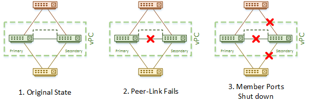
The peer-link is the most critical component of the vPC domain. If there is a peer-link failure, the switches can no longer share control information. Fortunately, due to the keepalive link, both peers are able to determine that both switches are up, and they will keep their primary and secondary roles.
In a case where the peer-link has failed, but both switches are still up, the secondary will immediately disable it’s vPC member ports. Only the primary will forward traffic. This prevents the duplication of frames and loops from forming. Unfortunately, it does ‘blackhole’ any orphan ports on the secondary switch.
If new member ports are configured while there is a peer-link failure, by default, the new ports will stay down. This happens because the peer-link is required to perform consistency checks on new ports. If existing member ports go down, they too will stay down until the peer-link outage is repaired. The auto-recovery command, discussed below, can help with this scenario.
Let’s imagine that you’re having a bad day. You’ve just found out that the peer-link in one of your vPC domains has failed. You’re not overly worried. You know that the secondary will shut down its member ports while the primary will continue forwarding traffic. You keep it cool, ready to work on the peer-link.
Then you’re day starts getting worse. The primary switch just failed. What’s going to happen? The keep-alive link will now fail, as the primary switch is down. The secondary gets suspicious when heartbeat messages stop coming in. When three consecutive messages are missed, the secondary goes into action. The secondary switch now transitions into the primary role and brings up its member ports. Traffic begins flowing again.
By default, keepalive messages are sent once every second. This scenario results in 3-4 seconds of traffic disruption.
Set the keepalive interval to 400ms (up to 10000ms)
Switch2(config)# vpc domain 10
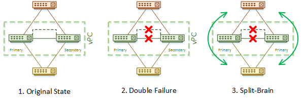
Switch2(config-vpc-domain)# peer-keepalive destination x.x.x.x source y.y.y.y vrf management timeout 400Let’s upgrade to a catastrophic day… You start with a healthy vPC domain, then the keep-alive link fails. So far, this is not a big deal, as the peer-link is still up. There is no disruption to traffic, and the roles do not change. Before you can repair it, the peer-link fails. This is the worst case scenario.
In the absense of keepalive messages, the secondary switch thinks that the primary has failed. It transitions into the operational primary role, and continues to forward traffic. Unfortunately, the configured primary thinks it’s alone, and also continues to forward traffic. There are now two primary switches, both forwarding traffic. This is called split brain or dual-active. This will require manual intervention to repair.
This also illustrates why it is important to keep spanning-tree enabled, even if vPC is used. In the diagrams below, the switches transition to a split-brain topology. As there are other switches connected, there is now a layer-2 loop. This is a case where spanning-tree kicks in to block one of the links and prevent the loop.
Auto Recovery
The default vPC settings make a lot of the recovery for peer-link failures a manual process. The auto-recovery command allows for much of this to be automated. It is especially useful in two scenarios:
If both switches reboot, and only one comes back, this one will automatically become the primary. If the peer-link and keepalive link do not come up after a period of time, the member ports are bought up. If the peer-link does comes up, but the keepalive link does not, both switches keep the member ports down
If the member ports are down on the secondary due to a peer-link failure, and then the primary fails, the secondary assumes the primary role. The member ports are brought up on the new primary. The new primary waits for three consecutive failures on the keepalive link before bringing the ports up
vpc domain 10
  auto-recovery reload-delay 240

! Verify
Switch-2# show vpc brief
Legend:
                (*) - local vPC is down, forwarding via vPC peer-link

vPC domain id                     : 10
Peer status                       : peer adjacency formed ok
vPC keep-alive status             : peer is alive
Configuration consistency status  : success
Per-vlan consistency status       : success
Type-2 consistency status         : success
vPC role                          : secondary
Number of vPCs configured         : 0
Peer Gateway                      : Disabled
Dual-active excluded VLANs        : -
Graceful Consistency Check        : Enabled
Auto-recovery status              : Enabled, timer is off.(timeout = 240s)    ! Auto recovery is now enabled
Delay-restore status              : Timer is off.(timeout = 30s)
Delay-restore SVI status          : Timer is off.(timeout = 10s)
Traffic Flow
vPC is tuned for flow symmetry. Under normal circumstances, a control-plane traffic flow will stick to one chassis, the primary. This avoids using the peer-link for unicast traffic. This is even true with HSRP/VRRP, which load-balances data-plane traffic, but uses a single switch for control plane traffic.
Part of what makes the data plane active/active, is the System MAC. The System MAC is a virtual MAC address for the vPC domain as a whole. This makes either switch capable of forwarding traffic sent to the domain.
There is a small problem with some devices though. When a client sends an ARP message, the primary switch responds. The response message contains the System MAC of the domain. The MAC address that the response is sent from is the real MAC of the primary switch. This MAC is sometimes called the BIA (Burned In Address), as it is physically allocated to this device.
When a device receives the ARP respsonse, it should look at the MAC in the response frame, and store it in its MAC table. Not all devices (such as NetApp and EMC SANs) follow this standard though. They use technologies such as MAC Based Forwarding instead. Instead of looking at the MAC address in the ARP response, it looks at the source address of the frame. This is the physical MAC address for the primary switch. The result is that they send all frames to the primary switch.
The secondary switch may receive some traffic with the primary switch’s MAC address as the destination. This might happen due to the way the connected device does port hashing on its LAG. When this happens, the secondary switch will try to forward the frame to the primary over the peer-link. This causes the duplicate frame rule to kick-in, and the frame is dropped.
The vPC solution to this problem is called Peer Gateway. The peer-gateway command allows the switch that receives a frame to respond with its peer’s BIA address. This means no unnecessary forwarding over the peer-link, and no frames getting dropped.
vpc domain 10
  peer-gateway
Config Synchronisation
vPC configuration has to match on both vPC peers. There are two ways of achieving this. One is to manually configure them to be the same. The other is to synchronise the configuration automatically.
Config Sync is not specific to vPC. It is part of the Nexus toolset. It involves creating a configuration profile, which then gets sent over the mgmt0 interface.
Use of config sync is outside the scope of this article.