
OSPF Design
Last Updated: [last-modified] (UTC)
Design Principle: Keep the design simple. Don’t overcomplicate
OSPF is a robust and scalable routing protocol. And, due to its open standard heritage, it’s also very popular.
On the surface, it’s more complicated than some other routing protocols. To deploy OSPF, you will need a little more thought and planning.
The upside is that it helps you to uncover problems in your topology and IP addressing scheme. The downside is that if you do not plan well, you may introduce scaling problems. The best advice is to design out the solution, but try to keep it simple. Don’t overcomplicate it.
As we’ll see in this article, common factors that affect scalability are:
- The amount of routing information per area
- The number of routers per area, and areas per router
- Link stability
- The number of neighbours
Topologies
Full and Partial Mesh
Use full mesh for high throughput and optimal routing. This would be common in the core.
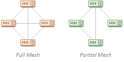
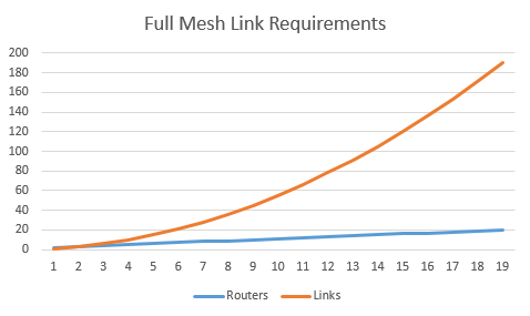
This can be expensive to implement, due to all the extra links in use. The number of links needed for the full mesh is n (n – 1) / 2. When the network grows, the number of links grows even faster. Also, scalability can be a concern. A full mesh means more neighbours per router, which increases flooding.
A partial-mesh topology may help as the network grows. This means fewer links and neighbour relationships. This is at the expense of having fewer paths.
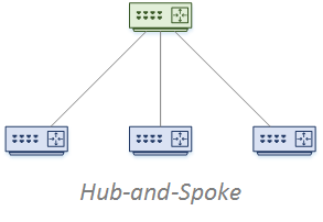
Hub and Spoke
A small network may use only area 0. But as the network grows, this can cause scalability concerns. Consider the impact of putting WAN spoke networks in area 0.
WAN links are less stable than LAN links. Every time a link flaps, the router generates LSA’s and floods them through the area. If the entire network is in a single area, the change floods through the entire network.
If you can, put spoke networks in a separate stub or totally stubby area. There is a balance to achieve. If you have a lot of spokes, you will end up with a lot of areas, and a lot of summarised networks in the backbone. Sometimes a few spokes may be in a single stub area.
Now imagine a spoke network that is a branch office. This branch office has spokes of its own, going to retail outlets. In a case like this, how far does the area extend? Is the branch part of Area 0? Are the branch and all its spokes part of a separate area?
A guideline here is to try to keep WAN links out of the backbone. Keep the backbone simple and manageable wherever possible, and always aim for stability.
Using point-to-point or point-to-multipoint links are good for convergence. But, this adds more routes to the OSPF database. Plan out the IP space if you can, to account for this.
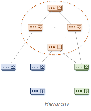
Hierarchy
The traditional campus and data centre topologies use a three-layer design. OSPF though, needs all areas to connect to Area 0. This means that OSPF only supports a two-layer hierarchy.
This doesn’t mean that OSPF can’t handle extra layers. It just takes more thought on your part. Like hub-and-spoke, you need to decide how far to extend the backbone area.
In a very large network, a hybrid solution may be useful. Maybe you could use iBGP in the core, and OSPF in the distribution and access layers. If you have a data centre, consider a separate OSPF instance. This is especially relevant if a different team administers it.
If you split the network into separate instances, think about where redistribution happens. The best place is to do this on the DR routers.
Area Design
Area Size
We’ve heard many times about keeping the routing table small. But the size of an area in OSPF is more than just the number of routes.
OSPF keeps a database of the entire area. This includes all the prefixes it knows as well as router information. Prefixes in the database are not necessarily in the routing table. The larger this database, the more information there is to synchronise during convergence.
Summarization limits the number of prefixes in the database. Another possibility is to use the prefix-suppression command. This hides networks on regular interfaces, only advertising loopback’s and secondary IP’s
Limiting the number of routers in an area helps. But how many is too many? In a normal area, Cisco recommends no more than 50 routers. The backbone area can go higher, up to 300 routers. But if you have this many routers in the area, you need a solid design.
Also, consider the MTU. Router information is sent in LSA packets. The more routers, the larger the LSA’s. If this reaches a point where the LSA’s are larger than the MTU, fragmentation will occur. This is too many routers in the area.
The number of ABR’s also affects area size. There is a summary LSA for each router in an area, which ABRs flood into other areas. As an example, in an area with five routers, three ABR’s will generate a total of 15 LSA’s. This shows that more ABR’s per area is not necessarily better.
As a side note, a refinement in RFC5185 allows a link between a pair of ABR’s, that are in many areas. This is for use in a hub-and-spoke topology.
Addressing
Design Principle: Use a good IP addressing scheme
A good addressing scheme enables good summarization. This reduces the amount of routing information per area. Smaller areas help with stability and scalability. This calls for a clearly defined backbone and area topology.
During OSPF design, map areas and ABR’s to parts of the network that are easily summarised.
When planning an IP scheme:
- Make the range of networks in an area contiguous
- Create a space that can split as the network grows
- Plan ahead for new routers to be added to the network
Backbone Area
Design Principle: The backbone should be fast and stable
The backbone area is for transport. All other areas rely on it. For this reason, there are a few recommendations for Area 0:
- Use high-quality links – Flapping links cause LSA flooding and reconvergence
- Limit the database size – A smaller database converges faster
- Make other areas stubs – This helps with summarization, which limits the routes in the backbone
- Avoid partitioning the backbone – A virtual link is a workaround, not a design
Stub Areas
Design Principle: Use stubby or totally stubby areas when possble
Stub areas cut down the number of routes in an area. A NSSA is a stub area that allows redistribution from other routing protocols. Totally stubby areas are Cisco proprietary and only allows a default route into the area.
The recommendation here is to use stubby areas to keep the number of routes in an area low. The lower the better.
Sometimes this can be a trade-off. In a totally stubby area, the ABR will send only the default route. This means that routers in an area can’t tell one ABR from another. More accurately, they can’t tell if one ABR has a better path to a network than another ABR. This may cause sub-optimal routing.
If you like the idea of using a totally stubby network, but need to leak a few networks, consider route filtering. Use a normal stub area, and then use prefix lists to filter the networks you don’t want. The big downside to this is a very manual process, and more difficult to maintain.
Summarisation and ABR’s
Design Principle: Use summarisation to reduce routes and increase stability
You should use summarization for two main reasons. The first is to limit the number of routes in an area. Especially in the backbone. Another reason is to minimise the impact of flapping links. Summaries prevent LSA flooding across areas.
Remember though, that ABR’s do not automatically summarize routes for you. They just pass routes from one area to another, and mark them as Inter-Area routes.
You, as the administrator, need to configure the appropriate summaries on the ABR’s.
Design Principle: Limit the number of ABRs and ASBRs per area
Cisco used to have a recommendation to have no more than three areas per ABR. Some articles out on the internet still put forth this recommendation.
A lot has changed since then, and these days it’s difficult to recommend an exact number. This all depends on the type of area, the number of routes, the router hardware, and so on.
Typically, most ABR’s will only have 2-3 areas anyway. But think about the example earlier of the branch office. This hub router may have many spoke networks, and therefore, many different areas.
The best bet is to monitor the router and OSPF performance. If needed, add more ABR’s to share the load.
Convergence
Modern applications drive the requirement for fast convergence. Voice and video in particular benefit from sub-second convergence.
Link Flapping
Every time there is a route change, the router generated LSA’s to notify neighbours. If a link is flapping, LSA’s continually flood the network, causing convergence events.
A hold-timer limits the impact of flooding. A router will wait until the hold timer expires before flooding the LSA’s. Cisco routers use an exponential back-off algorithm. This is a balance between converging quickly and limiting flooding.
This consists of three timers:
- Start Interval – The initial delay before flooding after a link change. This is 0ms by default
- Hold Interval – The minimum time to wait before flooding. This is 5s by default and doubles with each flap
- Max Interval – The maximum time the hold interval can increase to. This is 5s by default
What this means is, when a link flaps, the hold interval increases up to the max interval. The more a link flaps, the longer it waits until flooding. As the network stabilises, the timers reset.
The defaults show that this will only go to a maximum of 5 seconds. You may need to tune these values yourself according to your network needs. If you want to tune them, change the values gradually, and monitor the effect.
SPF Algorithm
OSPF uses LSA messages to notify neighbours of changes. When receiving an LSA, the SPF algorithm begins to run to calculate the best paths.
There is a downside to this. SPF runs when the first LSA arrives. So, if there are many LSA’s, the algorithm may run, then receive more LSA’s, then run again, and so on.
A strategy is to delay SPF a little to allow more LSA’s to arrive. SPF can then process them all at once. The delay can grow dynamically to further limit the impact of link flaps.
There are three timers in the process (defaults vary per platform):
- SPF Start – The initial delay before running SPF
- SPF Hold – This is the incremental value in the back-off algorithm. This should be higher than the time it takes to run SPF
- SPF Max Wait – This is the maximum value the hold timer can increase to
SPF can be further tuned with the Incremental SPF feature. This is where the algorithm is only run on the affected parts of the SPF tree. This saves resources in large networks, by not rebuilding the entire tree every time.
References
Cisco Live – BRKRST-2337 – OSPF Deployment in Modern Networks
Marwan Al-shawi and Andre Laurent – Designing for Cisco Network Service Architectures (ARCH) Foundation Learning Guide: CCDP ARCH 300-320 (ISBN 158714462X)