
VRF Lite
Virtual Routing Tables
A VRF is either VPN Routing and Forwarding or Virtual Routing and Forwarding. It depends who you ask. What matters though, is what it does.
Every layer-3 device has a routing table. The device uses the routing table to make routing decisions. But did you know that some devices have several routing tables? That’s what VRF’s are all about.
A VRF is a virtual routing table
Each VRF is an extra routing table. Generally, only routers support VRF’s, not all layer-3 devices. But why would you need several routing tables? There are a few reasons, which will be revealed throughout this article. The most common is to many customers, while keeping them separate.
Are you familiar with VLANs? VLANs separate traffic on a switch at layer-2. VRF’s are similar, as they separate traffic on a router at layer-3.
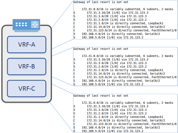
To help with understanding this, have a look at the diagram below. This is a single router with three VRF’s. Each VRF is a completely separate routing table. Routes in one VRF may overlap with routes in another VRF. This is not a problem at all, and can be quite useful.
When creating extra VRF’s, the original routing table still exists. It is the default VRF, also known as the global routing table.
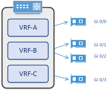
So, how do routes get into a VRF? The first step is to understand how VRF’s and interfaces play together. Every interface on a router is in one VRF. That means that every interface is in a VRF. To start with, every interface is in the default VRF. As more VRFs are created, interfaces can be assigned to them. These interfaces may be physical, or virtual, such as a VLAN SVI or loopback.
When an interface has an IP address assigned, that network appears in the VRF as a connected route. This is the same behaviour as in the global routing table.
By default, networks in one VRF cannot communicate with networks in another VRF. Under some circumstances, this behaviour changes, but more on that later.
VRF vs VRF-Lite
So far, we’ve talked about VRF’s. But what about VRF-Lite? After all, that’s what this article is about right? Are they the same thing? Hmmm… Sort of. It’s a terminology thing.
MPLS VPN deployments use VRF’s. This is often used by service providers so their customers can share the network. These deployments use BGP for routing, which is VRF aware.
Other deployments will use VRF’s, but will not use MPLS and BGP. This is VRF-Lite. Often VRF-Lite deployments are called VRF’s, which is fine.
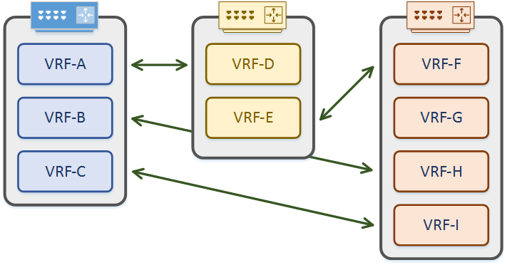
This is a good time to emphasis that VRF’s are locally significant to each router. A VRF on one router does not need to match a VRF on another router. Remember that they are routing tables. It’s like having several virtual routers running at once.
As shown below, interfaces from various VRF’s may connect to VRF’s from any other router. Names and configuration does not need to match in any way. All they need is suitable IP addressing.
Use Cases
So what would you use VRF’s for? Good question! As already mentioned, one use is to separate customer traffic. This is particularly useful for service providers and modern multi-tenanted data centres.
Another reason is because they allow IP spaces to overlap. Why would you ever design your network with overlapping IP address spaces? In a perfect world, you wouldn’t. But your company may merge with other companies that use the same space as you. If this happens, you could re-address the network, use NAT, or use VRF’s. The solution may be a combination of all three?
Do you have guest WiFi? Or, public kiosk computers? You will want to keep their traffic separate from your corporate network. VRF’s may be the solution you’re looking for.
OK, time for one more. Imagine that you have virtual machines that connect to a layer-3 switch. These are in two Business Units. VM’s from one BU should not talk to VM’s from the other BU without passing through a firewall. In this case each BU could have a VRF. Each VRF could have a default route to a firewall. As traffic can’t pass between the VRF’s, it will have to go out through the firewall, and back in to the other VRF. This is an interesting scenario… Lets look deeper into that soon.
Example 1: VRF-Lite
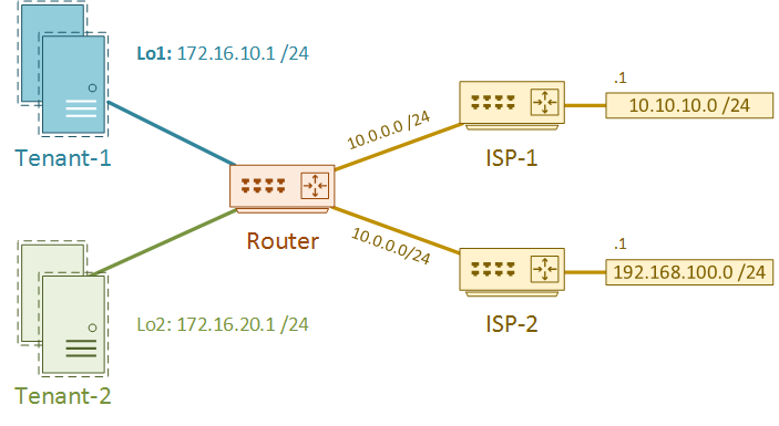
First, a simple scenario. Look at the diagram below. There is a single physical Layer-3 switch, with VM’s attached. The VM’s belong to two different tenants, and their traffic should not mix.
The default gateway for each VM is an SVI on the switch. This allows traffic to pass from one tenant to another, which is unacceptable.
To resolve this, we need to create a VRF for each tenant. Each VRF will have an interface connecting to ISP routers. This is how the tenants will get internet access.
For lab purposes, the ISP-1 and ISP-2 routers are already configured. They are not aware of VRF’s, so they only have the global routing table. Two loopback interfaces represent the two tenants.
The goal of the lab is to
- Create two VRF’s, one for each tenant
- Create loopback interfaces, to represent the two tenants
- Configure the interfaces that connect to the ISP routers
- Add routes for each tenant
- Test tenant traffic isolation
The VRF must exist before it can be used. In IOS, this includes specifying each address-family that the VRF supports. Other implementations, such as NXOS, do not need an address-family.
This lab will only use the IPv4 address family.
Router(config)#vrf definition ISP-1
Router(config-vrf)#address-family ipv4
Router(config-vrf-af)#exit
Router(config-vrf)#vrf definition ISP-2
Router(config-vrf)#address-family ipv4
Every interface belongs to a single VRF. If an interface has no VRF specified, the interface belongs to the default VRF. Use the vrf forwarding command on the interface to associate an interface with the VRF.
Here’s an important fact to remember. Any L3 config on an interface is removed when associating the interface with a VRF. So, remember to configure the VRF first, then the IP address.
Router(config)#int gi 0/1
Router(config-if)#ip address 10.0.0.1 255.255.255.0
Router(config-if)#vrf forwarding ISP-1
% Interface GigabitEthernet0/1 IPv4 disabled and address(es) removed due to enabling VRF ISP-1

Router(config-if)#ip address 10.0.0.1 255.255.255.0
Router(config-if)#no shut
Router(config-if)#exit
*Mar 20 01:42:03.473: %LINK-3-UPDOWN: Interface GigabitEthernet0/1, changed state to up
*Mar 20 01:42:04.472: %LINEPROTO-5-UPDOWN: Line protocol on Interface GigabitEthernet0/1, changed state to

Router(config)#int gi 0/2
Router(config-if)#vrf forwarding ISP-2
Router(config-if)#ip address 10.0.0.1 255.255.255.0
Router(config-if)#no shut
*Mar 20 01:42:38.702: %LINK-3-UPDOWN: Interface GigabitEthernet0/2, changed state to up
*Mar 20 01:42:39.702: %LINEPROTO-5-UPDOWN: Line protocol on Interface GigabitEthernet0/2, changed state to up

Router(config)#int loopback 1
Router(config-if)#vrf forwarding ISP-1
Router(config-if)#ip address 172.16.10.1 255.255.255.0

Router(config)#int loopback 2
Router(config-if)#vrf forwarding ISP-2
Router(config-if)#ip address 172.16.20.1 255.255.255.0
Static routes can also be associated with a VRF. For this lab, there are two default routes. That is, one default route for each tenant.
Router(config)#ip route vrf ISP-1 0.0.0.0 0.0.0.0 10.0.0.2
Router(config)#ip route vrf ISP-2 0.0.0.0 0.0.0.0 10.0.0.2
Have a look at the routing table. The default VRF, AKA the global routing table, has no routes at all.
ISP-1 and ISP-2 VRF’s have the static routes, as well as local and connected routes.
Router#show ip route
Codes: L - local, C - connected, S - static, R - RIP, M - mobile, B - BGP

Gateway of last resort is not set

Router#show ip route vrf ISP-1
Routing Table: ISP-1
Codes: L - local, C - connected, S - static, R - RIP, M - mobile, B - BGP

Gateway of last resort is 10.0.0.2 to network 0.0.0.0

S*    0.0.0.0/0 [1/0] via 10.0.0.2
      10.0.0.0/8 is variably subnetted, 2 subnets, 2 masks
C        10.0.0.0/24 is directly connected, GigabitEthernet0/1
L        10.0.0.1/32 is directly connected, GigabitEthernet0/1
      172.16.0.0/16 is variably subnetted, 2 subnets, 2 masks
C        172.16.10.0/24 is directly connected, Loopback1
L        172.16.10.1/32 is directly connected, Loopback1

Router#show ip route vrf ISP-2

Routing Table: ISP-2
Codes: L - local, C - connected, S - static, R - RIP, M - mobile, B - BGP

Gateway of last resort is 10.0.0.2 to network 0.0.0.0

S*    0.0.0.0/0 [1/0] via 10.0.0.2
      10.0.0.0/8 is variably subnetted, 2 subnets, 2 masks
C        10.0.0.0/24 is directly connected, GigabitEthernet0/2
L        10.0.0.1/32 is directly connected, GigabitEthernet0/2
      172.16.0.0/16 is variably subnetted, 2 subnets, 2 masks
C        172.16.20.0/24 is directly connected, Loopback2
L        172.16.20.1/32 is directly connected, Loopback2
Below, the ping to 10.0.0.1 fails. This happens because the ping is using the default VRF. To use a different VRF, specify the VRF in the ping command.
Router#ping 10.0.0.1
Type escape sequence to abort.
Sending 5, 100-byte ICMP Echos to 10.0.0.1, timeout is 2 seconds:
.....
Success rate is 0 percent (0/5)

Router#ping vrf ISP-1 10.0.0.1
Type escape sequence to abort.
Sending 5, 100-byte ICMP Echos to 10.0.0.1, timeout is 2 seconds:
!!!!!
Success rate is 100 percent (5/5), round-trip min/avg/max = 2/3/6 ms

Router#ping vrf ISP-2 10.0.0.1
Type escape sequence to abort.
Sending 5, 100-byte ICMP Echos to 10.0.0.1, timeout is 2 seconds:
!!!!!
Success rate is 100 percent (5/5), round-trip min/avg/max = 3/3/3 ms
The ISP networks are reachable. Notice that tenants in the ISP-1 VRF cannot ping networks in the ISP-2 VRF.
Router#ping vrf ISP-1 10.10.10.1
Type escape sequence to abort.
Sending 5, 100-byte ICMP Echos to 10.10.10.1, timeout is 2 seconds:
!!!!!
Success rate is 100 percent (5/5), round-trip min/avg/max = 3/4/5 ms

Router#ping vrf ISP-1 192.168.100.1
Type escape sequence to abort.
Sending 5, 100-byte ICMP Echos to 192.168.100.1, timeout is 2 seconds:
.....
Success rate is 0 percent (0/5)

Router#ping vrf ISP-2 192.168.100.1
Type escape sequence to abort.
Sending 5, 100-byte ICMP Echos to 192.168.100.1, timeout is 2 seconds:
!!!!!
Success rate is 100 percent (5/5), round-trip min/avg/max = 4/5/7 ms
Dynamic Routing
What if you want to run OSPF or EIGRP? Is this possible? Sure is!
Let’s assume we want to run OSPF. There are two ways to approach this. Each VRF can run its own OSPF process. This provides the best traffic isolation, but there is a limited number of processes. The other way is to run OSPF as a single process. Each VRF is still isolated, but there’s a risk. Faults with the process would affect all VRF’s. For example, if you removed the OSPF process, routing would break for all VRF’s.
What if you want to share routes? There are two ways to do this. One way is to use MP-BGP to leak routes from one VRF to another. This is an interesting topic, but is beyond the scope of this article.
The other is with traffic hair-pinning. This is where an external router or bridge connects to both VRF’s. Let’s look at an example of that.
Example 2: Hair-Pinning
This is going to build on the previous example. Let’s assume that it’s ok for tenant 1 to connect to tenant 2, as long as traffic passes through a firewall. In this case, the firewall can have an interface connected to each VRF on the switch. This might be two physical interfaces, or a single physical interface with sub-interfaces.
A simplified topology would look like this:
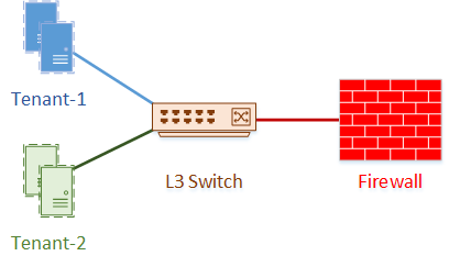
The switch and firewall both run OSPF. The VM’s use the switch as their default gateway. Traffic from tenant-1 passes to the switch, then out of the VRF to the firewall. From the firewall, the traffic passes into tenant 2’s VRF on the switch, then to the appropriate VM.
The firewall does not use VRF’s itself, and is preconfigured in this lab.
To allow this to work, the IP of gigabit 0/2 is now 10.0.20.1. The static routes are also removed.
Below, OSPF is configured on the L3 switch, which peers with the firewall.
! Gi0/2 has been changed to 10.0.20.1
! Static routes have been removed

Router(config)#router ospf 10 vrf ISP-1
Router(config-router)#network 172.16.10.0 0.0.0.255 area 0
Router(config-router)#network 10.0.0.0 0.0.0.255 area 0
*Mar 21 01:40:43.150: %OSPF-5-ADJCHG: Process 10, Nbr 10.0.20.2 on GigabitEthernet0/1 from LOADING to FULL, Loading Done

Router(config)#router ospf 20 vrf ISP-2
Router(config-router)#network 172.16.20.0 0.0.0.255 area 0
Router(config-router)#network 10.0.20.0 0.0.0.255 area 0
*Mar 21 01:41:53.148: %OSPF-5-ADJCHG: Process 20, Nbr 10.0.20.2 on GigabitEthernet0/2 from LOADING to FULL, Loading Done
Routes for both tenants are now appearing in both VRF’s. The difference is that the next hop for other tenant networks is the firewall, which OSPF learns.
Router#sh ip route vrf ISP-1

Routing Table: ISP-1
Codes: L - local, C - connected, S - static, R - RIP, M - mobile, B - BGP
Gateway of last resort is not set

      10.0.0.0/8 is variably subnetted, 3 subnets, 2 masks
C        10.0.0.0/24 is directly connected, GigabitEthernet0/1
L        10.0.0.1/32 is directly connected, GigabitEthernet0/1
O        10.0.20.0/24 [110/2] via 10.0.0.2, 00:01:34, GigabitEthernet0/1
      172.16.0.0/16 is variably subnetted, 3 subnets, 2 masks
C        172.16.10.0/24 is directly connected, Loopback1
L        172.16.10.1/32 is directly connected, Loopback1
O        172.16.20.1/32 [110/3] via 10.0.0.2, 00:00:29, GigabitEthernet0/1

Router#sh ip route vrf ISP-2

Routing Table: ISP-2
Codes: L - local, C - connected, S - static, R - RIP, M - mobile, B - BGP
Gateway of last resort is not set

      10.0.0.0/8 is variably subnetted, 3 subnets, 2 masks
O        10.0.0.0/24 [110/2] via 10.0.20.2, 00:00:40, GigabitEthernet0/2
C        10.0.20.0/24 is directly connected, GigabitEthernet0/2
L        10.0.20.1/32 is directly connected, GigabitEthernet0/2
      172.16.0.0/16 is variably subnetted, 3 subnets, 2 masks
O        172.16.10.1/32 [110/3] via 10.0.20.2, 00:00:40, GigabitEthernet0/2
C        172.16.20.0/24 is directly connected, Loopback2
L        172.16.20.1/32 is directly connected, Loopback2
Ping and traceroute show that traffic between tenants is passing through the firewall. This allows the firewall to inspect the traffic, and apply security policies.
Router#ping vrf ISP-1 172.16.20.1 source 172.16.10.1
Type escape sequence to abort.
Sending 5, 100-byte ICMP Echos to 172.16.20.1, timeout is 2 seconds:
Packet sent with a source address of 172.16.10.1
!!!!!
Success rate is 100 percent (5/5), round-trip min/avg/max = 5/5/8 ms

Router#traceroute vrf ISP-1 172.16.20.1 source 172.16.10.1
Type escape sequence to abort.
Tracing the route to 172.16.20.1
VRF info: (vrf in name/id, vrf out name/id)
  1 10.0.0.2 8 msec 6 msec 7 msec
  2 10.0.20.1 5 msec 9 msec *

Router#ping vrf ISP-2 172.16.10.1 source 172.16.20.1
Type escape sequence to abort.
Sending 5, 100-byte ICMP Echos to 172.16.10.1, timeout is 2 seconds:
Packet sent with a source address of 172.16.20.1
!!!!!
Success rate is 100 percent (5/5), round-trip min/avg/max = 4/7/10 ms

Router#traceroute vrf ISP-2 172.16.10.1 source 172.16.20.1
Type escape sequence to abort.
Tracing the route to 172.16.10.1
VRF info: (vrf in name/id, vrf out name/id)
  1 10.0.20.2 7 msec 4 msec 5 msec
  2 10.0.0.1 7 msec 8 msec *