Back to Back vPC
Last Updated: [last-modified] (UTC)
Introduction
A back-to-back vPC is a way of connecting two pairs of Nexus switches with vPC. Depending on the documentation, it is also known as Multi-Layer vPC or Double-Sided vPC.
When a device connects to a pair of switches, it will do so with a regular port channel or LAG. It is unaware that there is a vPC at the other end. From the device’s perspective, it connects to a single switch.
A back-to-back vPC is similar, except that there is a vPC at both ends. In this way, both ends think they have a connection to a single switch. The logical topology is two switches with a port channel between.
There are two topologies that use back-to-back vPC’s. One is at the aggregation layer, where a full mesh of links is usually used. The other is between data centres. This uses a partial-mesh of DCI links. A third option is a hybrid approach, which mixes the two topologies.
Aggregation Layer
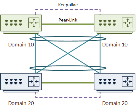
A common back-to-back vPC topology is between the aggregation layer and the access layer. This uses a full mesh of links between the pair, as shown below. This is not typically used between the core and aggregation layers. These are normally routed links, while vPC is a layer-2 technology.
It is worth mentioning that the Nexus models do not have to be the same across the switch pairs. For example, the aggregation layer may have a pair of N7K’s, while the access layer may use a pair of N5K’s.
The vPC domain ID’s must be different between the switch pairs. In the diagram below, there are four ports used in each pair. All four ports are in the same port-channel.

DCI Links
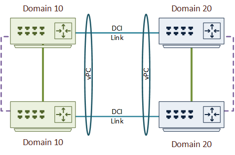
Data centre connectivity can benefit from back-to-back vPC. This is similar to the implementation at the aggregation layer. Although, this usually won’t involve a full mesh of links, as they’re quite expensive.
Cisco’s recommendation is to only use this to connect only two data centres. If you need to connect more, look into another technology, such as OTV or VxLAN.
When using a topology like this, the best practice is to enable BPDU filter on the DCI links. The switches will not send BPDU’s between the data centres. This means that each data centre will have its own spanning tree domain and root bridge. This is a good reason why only two data centres should be connected like this. If you connect more, you may end up with a loop that spanning tree does not detect.
The DCI link ports should be edge ports. This implements portfast, which allows the links to come up faster after a failure.

Hybrid Topology
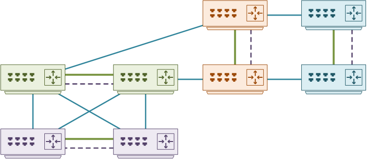
The two previous topologies can be mixed into a hybrid topology. There are three vPC’s shown below:
- Between the aggregation layer (green) and the access layer (purple)
- Between the data centre edge (orange) and another data centre (blue) over DCI links
- Between the data centre edge (orange) and the aggregation layer (green)
There are a few guidelines for doing this. Firstly, all pairs should use different vPC domains. In the example below, there would be four different vPC domains.
Secondly, a separate set of switches should be used for aggregation and DCI links. This means that the aggregation switches should not also be the edge switches. An alternative would be to use separate VDC’s on N7K switches.

Configuration
Before configuring your switches, select the interfaces that will be in the vPC. For example, in a fully meshed back-to-back vPC, you will likely choose 4 or 8 ports across the two switches. Next, select port channel numbers for each pair. As shown in the example, they don’t have to be the same for each pair.
The example below is for a fully meshed back to back vPC between the aggregation layer and the access layer. The example assumes that the basic vPC topology has already been configured. The domain ID’s should be different in each pair.
Ethernet 1/1-2 on each switch will be in the vPC. This is a total of four ports across the pair. All four ports are added to port channel 10 on the first pair, and port channel 20 on the second pair.
! Add the four interfaces to a portchannel
int eth1/1-2
  channel-group 10 mode active

!Add the port channel to a vPC
int po 10
  vpc 10

! Repeat for the second switch in the pair
! Add the four interfaces to a portchannel
int eth1/1-2
  channel-group 20 mode active

!Add the port channel to a vPC
int po 20
  vpc 20

! Repeat for the second switch in the pair
Switch-1# show vpc brief
Legend:
                (*) - local vPC is down, forwarding via vPC peer-link
vPC domain id                     : 10
Peer status                       : peer adjacency formed ok
vPC keep-alive status             : peer is alive
Configuration consistency status  : success
Per-vlan consistency status       : success
Type-2 consistency status         : success
vPC role                          : primary
Number of vPCs configured         : 12
Peer Gateway                      : Enabled
Peer gateway excluded VLANs     : -
Dual-active excluded VLANs        : -
Graceful Consistency Check        : Enabled
Auto-recovery status              : Enabled (timeout = 240 seconds)
vPC Peer-link status
---------------------------------------------------------------------
id   Port   Status Active vlans
--   ----   ------ --------------------------------------------------
1    Po100  up     1,500

vPC status
----------------------------------------------------------------------------
id     Port        Status Consistency Reason                     Active vlans
------ ----------- ------ ----------- -------------------------- -----------
11     Po10        up     success     success                    500
Page 54 of this document says the opposite you do:
https://www.cisco.com/c/dam/en/us/td/docs/switches/datacenter/sw/design/vpc_design/vpc_best_practices_design_guide.pdf
For ease of configuration and operations, best practice is to use same port-channel id and same vPC id on both vPC domains for the interconnect link (i.e vPC in the middle of the 2 vPC domains).
Care to explain why you think otherwise?
Hi,
Each vpc cluster (not depending on which nexuses it’s built 5k or 7k) has to have unique vpc domain name. The reason is that both peers in the domain create virtual MAC address and use it as ID for all VPC LACP port-channels.
And if you will try to interconnect two clusters with such links there will be a conflict of ID’s which will cause instability.