
Hierarchy Design – Part 1
The campus hierarchy uses three logical layers; Core, distribution, and access. Each layer has a special purpose to fulfil, so it’s important to use a proper design.
Key design point: Design deterministically
When designing, remember to be deterministic. One advantage of this approach is modularity. This supports rapid template-like deployment of switch blocks. They will scale well, and will follow a known behaviour when recovering from failures. A deterministic network is also easy to understand, troubleshoot, and document.Does this mean that non-deterministic networks are no good? No, they can still work, and they may work well. But, they carry a downside. For instance, imagine a new staff member trying to learn the network. It can be quite difficult to pick up a network that’s full of workarounds, corner cases, and caveats. This results in a small group of people knowing the network well, and they’re the ones who get all the phone calls.The rest of this article will look at some ways to design the campus hierarchy in a deterministic way.
Switching and Routing in the Access Layer
The connection from access to distribution may be either switched or routed. The switched access topology uses trunks between the layers. In the routed access topology, the links use routed ports.The key differences between these topologies is the location of the layer-3 boundary. This affects other characteristics, such high-availability and traffic distribution.There are four access layer topology designs:
- Routed – Layer-3 Access Layer
- Traditional – Layer-2 Access layer
- Simplified Layer-2 – Using Virtual Switches
- Campus Fabrics – Using an overlay
Key design point: Limit VLAN spanning
There is a key design point to consider when selecting one topology over another. Does my network need to have VLANs spanning between access layer switches? The goal is to limit VLAN spanning whenever possible.When considering this, start by understanding the applications in your network. Then work out if they require the VLAN spanning. If they do, will this affect all distribution blocks, or could you isolate them to one or a few?
Routed Access Layer
In the routed access layer topology, all uplinks are layer-3 routed ports. There are no links between access layer switches.
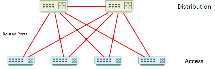
Every single uplink port uses the no switchport command. Each link is a /30 or /31 point-to-point link. If it’s easier for you to visualise this solution, think of each access switch as a small WAN site.
Dynamic routing shares reachability information. While it is possible to use static routing, it’s best to avoid it because of its complexity. EIGRP or OSPF are often used, but IS-IS and BGP are also valid choices.
In this topology, FHRP’s are not used at all. Each connected device uses an SVI on the access layer switch as its default gateway.
So why would you want to use this topology? The most obvious advantage is that there will not be any layer-2 loops. This means that there’s no need for spanning-tree to be blocking links. Having said that, don’t disable spanning-tree. It’s still needed in case someone were to connect two edge ports. This could be accidental or malicious.
The routed uplinks all have the same metric or cost, which enables ECMP. This means that the routing protocols don’t need to reconverge, enabling faster recovery. This is deterministic behaviour, as it’s clear how a failure will affect the network. Reconvergence is non-deterministic, as the recovery process depends on various factors. These include the size of the routing table, the number of neighbours, how busy the neighbours are, and so on.
Troubleshooting is simpler in this topology. There is a single set of tools to use across all layers. This is in contrast to spanning-tree at the access layer and routing at the core. As there is no HSRP, VRRP, or GLBP, there is no need to troubleshoot them.
Key design point: Routed access design prevents VLAN spanning
Sounds like a great topology, but is it the right choice for you? There’s a few critical points to be aware of.
The biggest point, is that VLANs will not span access switches. This is not a bad thing, as end-to-end VLANs are not generally recommended anyway. You may not have a choice though. There are still some legacy applications that need layer-2 adjacency. Sometimes, voice guys prefer a single VLAN for voice traffic, which is not possible in this model.
Using routed ports in the access layer means that all switches must be layer-3 capable. Switches that support features like routing are a little more expensive. Additionally, features like RSPAN will not work (although ERSPAN will).
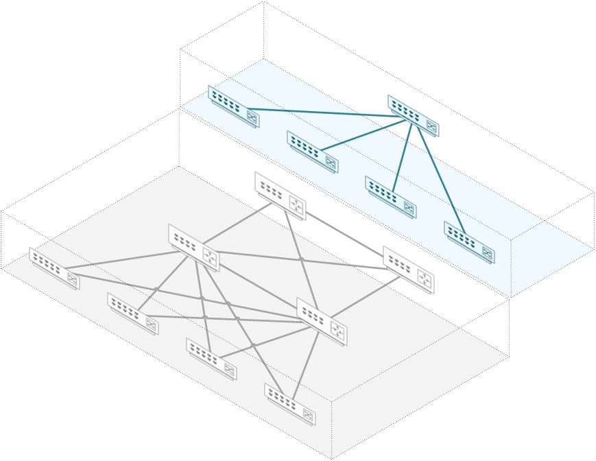
Virtual Switch
Routed access looks good, but what if you must span VLANs across the access layer?
Loops form when there are many devices all connected together in a circular fashion. At layer-2, spanning-tree blocks links to prevent this from happening, which isn’t ideal. One option would be to have less devices to avoid physical loops. But that’s no good, as we need redundancy. What about a virtual switch?
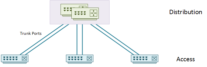
As shown below, the two distribution switches are a single virtual switch. This prevents loops without relying on spanning-tree, and still maintains high availability.
An mLAG or switch-stacking achieves this type of topology. With stacking, two or more switches are daisy-chained together with special stacking cabling. They act as a single switch from a control plane perspective. StackWise is Cisco’s version, while other vendors have their own implementations.
An mLAG, or Multi-chassis LAG, is a way of joining a pair of switches, to act as a single switch. Depending on platform, Cisco offer VSS or vPC. Other vendors have similar solutions as well, such as VLT. mLAG is different from stacking in the control plane, and it doesn’t need special cabling.
In this topology, the distribution layer uses SVI’s to act as the end host default gateways. FHRP is not required in a VSS or stacking solution. The SVI’s have IP helper enabled for dynamic addressing for the clients.
The access layer connects to the distribution layer using etherchannels. Physical cables go to two or more switches. From the access switch point of view, this is a normal etherchannel. LACP manages the etherchannel (or LAG), and has the advantage of working with other vendors.
From an mLAG perspective, VSS is often used in the campus, as it is supported on the Catalyst platform. vPC is used in the data centre, as it is a Nexus technology. As a simple summary, two VSS switches share a control plane, while vPC switches do not. This article focuses more on VSS.
The link between the VSS switches is the Virtual Switch Link (VSL). If this link were to go down, the switch pair could go into dual-active mode. This needs to be detected and handled to prevent loops.
There are three different methods to detect this type of failure:
- For a layer-3 link, BiDirectional Forwarding (BFD) messages can detect the failure
- For a layer-2 link, enhanced PaGP can detect the failure
- For a layer-2 link, fast hello messages can be forwarded over a separate out-of-band link
After detecting a VSL failure, it needs to be handled. To do this, one switch will shut down its ports, while the other continues forwarding traffic. This keeps traffic up while preventing loops.
There are many advantages to using this topology. One is that VSS eliminates the need for FHRP’s and spanning-tree. This makes configuration and troubleshooting easier. Additionally, all links are active and forwarding all the time. This is good for efficiency, but also helps optimise convergence if there is a link failure.
The best feature is the flexibility of this model. VLAN spanning is possible while preventing loops, and improving bandwidth. This is a simplified model, and there is less complexity in the control plane. There is no need for routing protocol convergence in the access layer, as LACP manages the links. LACP also balances traffic in a better way that spanning-tree does.
There is always a downside to any topology, and this has two notable ones. Only some platforms will support this feature. This can increase the cost of the distribution layer. Additionally, this requires some knowledge around stacking or VSS, for troubleshooting.
Layer-2 (AKA, Multi-Tier)
The traditional hierarchical design has access and distribution connecting at layer-2. This is useful when VLANs need to span end-to-end, and when virtual switching is not an option.
In this topology, the distribution layer switches will run some type of FHRP. The end hosts use the distribution layer as their default gateway.
At a high-level, there are two variations on this topology. These are the Loop-Free topology, and the Looped topology.
Loop Free Topology
This topology allows layer 2 between access and distribution, while removing physical loops. This means that spanning-tree will not need to block any paths.
There are two ways to do this. The first way is the Inverted-U topology. In this deployment, access layer switches are not connected to each other. Also, each access-layer switch connects to only one distribution switch. The distribution layer switches have a layer-2 link between them. There may be a layer-3 link as well, but it does not affect this design.
As you can see in the diagram below, this creates an inverted ‘U’ shape of layer-2 links.
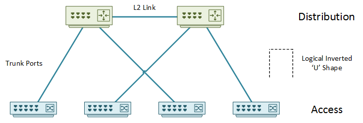
The problem with this design is that there are single points of failure. The failure of an upstream distribution isolates the access layer switches.
The second variant is a ‘U’ topology. In this model, there are layer-2 links between access switches. The distribution switches connect with a layer-3 link only. As you can see below, this creates a ‘U’ shape of layer-2 links.
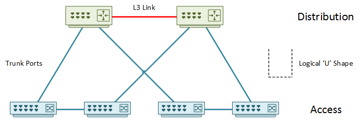
The layer-3 link breaks the layer-2 loop. Spanning-tree, while still enabled, will not be active and will not block links. This makes this design like the routed design, with the flexibility of VLAN spanning between the pair of switches. This does limit VLAN’s to the pair of access switches. They cannot be extended beyond the pair.
Limiting the VLAN propagation across the network also limits unknown unicast flooding. There is a lower risk of broadcast storms, and both uplinks to the distribution are active with GLBP.
Be careful with the links between access layer switches. In the example above, adding a link between the second and third access layer switch would cause a loop. Spanning-tree would need to start blocking links. This means that there can be only two access layer switches connected per VLAN.
Looped Topology
The looped topology uses layer-2 everywhere between access and distribution layer. This is the most flexible deployment for VLAN spanning, at the cost blocking links. In this design, it is critical to get the spanning-tree design right.
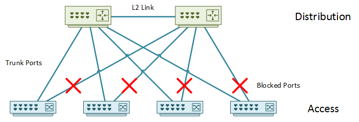
The uplinks can form a square or triangle shape. In a square topology, access switches connect only to a single distribution switch. A link between access layer switches provides redundancy. Both uplinks are forwarding, and the link between the access switches are blocking.
The triangle topology (above) has a link between each access and distribution switch. In this model, the link to one of the distribution switches is blocking. You could add a link between access layer switches, but it would block as well, which wouldn’t add much value.
The square topology is common if links to the distribution layer are expensive. This is not a typical constraint in the campus though.
This model, while allowing VLANs to span, is not very flexible or scalable in other areas. Avoid the multi-tier model if possible, and focus on either the routed or the virtual switch model.
Campus Fabric
A newer option is to use a network fabric with an overlay. Overlay’s have been around in the WAN for a while (MPLS), and are becoming more common in the data centre too with VxLAN.
In this model, the base base topology is a normal routed hierarchical network. This forms the underlay.
An overlay protocol, such as VxLAN or FabricPath is then configured. The overlay is a way of running a virtual network on top of a physical one.
This virtual network creates an abstraction. The connected hosts think that they’re in a large flat layer-2 network.
This has the advantage of allowing VLANs to span end-to-end. Due to routing in the underlay, spanning-tree does not block links.
This technology allows sending broadcast and unknown unicast traffic using multicast. This limits flooding in each VLAN.
Use VRF’s in this approach to deploy several virtual networks in the overlay. This allows business unit separation. A good example of this is to separate the guest network from the production network.
This is a more complicated approach to start with, and may need some new skills to operate. This solution in particular can make good use of automation.
Migrated Comment:
i like your references….
arteq 2018-01-24 01:27
thanks, i’ve been looking your site over last couple of days…
well done…
arteq
Migrated Comment:
Thanks
Luke Robertson 2018-01-24 10:18
Thanks Arteq, I appreciate the feedback