
VxLAN Bridging Configuration
The simplest VxLAN model is data-plane learning. It’s also known as ‘bridging’, as it acts as a layer-2 bridge between hosts.
This was the very first method of deploying VxLAN, and while it’s simple, it comes with some downsides.
As the ‘flood and learn’ suggests, some traffic is flooded through the underlay. It’s a lot like regular ethernet in this way. Also, there’s no built-in support for routing. If you need to route between VNI’s, you need an external router.
This method was eventually improved on by adding Control Plane Learning with BGP EVPN. You may be wondering, “Why should I bother with data-plane learning?” Well, the simple answer is that it’s much easier to understand. If you’re learning VxLAN, start here, and then move on to Control Plane Learning.
Let’s take a moment for a quick review of how VxLAN works, and how it will relate to this lab.
Hosts connect to a switch port. This may be a virtual switch or a physical switch. Many virtual machines and physcial hosts are unaware of VxLAN themselves. The exception is hypervisors, which may implement VxLAN in their virtual switching.
If the switch is mapping a VLAN to a VNI, the switch is a VxLAN gateway. The host port is an access port, which assigns a VLAN ID to all traffic that passes through it.
Each VxLAN switch has a VTEP interface. In the Nexus family, this is a virtual interface called an NVE interface. The NVE gets a /32 IP address from a loopback interface, which is advertised into the IGP
The NVE has one or more VNI’s bound to it. This is how the VTEP gets access to the LAN segments in the overlay.
Each VNI is also bound to a multicast group. This is how the switch is able to handle BUM traffic.
Configuration Environment
In the VxLAN Overview we talked about the Spine / Leaf topology. Well guess what? We’re not going to use it here.
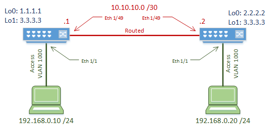
Why not? Because we’re keeping it simple. For learning purposes, we’re keeping this to a simple two-switch topology. The switches are connected with a routed link, which will act as our underlay.
A host is connected to each switch. The host ports are normal access ports, on VLAN 1000. The hosts are in the same subnet, and will not be able to communicate initially due to the routed link.
The switches are VxLAN gateways, which map VLAN 1000 to VNI 5000.
The switches used in this lab are Nexus 9000 EX Series, running 7.0(3)I5(2).
Underlay Configuration
The underlay is the routed portion of the network. In this lab, this is the link between the two switches.
It is important that the underlay is configured and working before the overlay is configured. Problems in the underlay will lead to problems in the overlay.
We start by enabling the OSPF and PIM features. OSPF is used to manage dynamic routing. Any IGP can be used here. PIM is multicast, which is used to handle BUM traffic.
VxLAN adds quite a bit of overhead, so we need to increase the MTU size. If we don’t do this, we may end up with fragmented packets, which can decrease performance.
We also need to start the OSPF process. We’ll add more OSPF config later on.
feature ospf
feature pim

system jumbomtu 9216

router ospf 10
This solution uses two loopback interfaces per switch.
Loopback0 is where the VTEP get’s its IP address from. This is a /32 address that needs to be advertised in OSPF and is different on each switch.
The IP in loopback0 is also used as the multicast Rendevouz Point address. This is enhanced with loopback1, which is the RP anycast address. Notice that this address is the same on both switches.
The multicast config is quite simple in this lab. Each interface is configured in sparse mode. Anycast Rendevouz Points are used for high availability. RP’s would typically be assigned to the spine switches in a real-world topology.
These RP’s are responsible for all multicast groups (224.0.0.0/4) for the purposes of this lab. In production, you should narrow this down a bit.
Now to configure the routed link. There’s nothing really special here. It’s a routed port, its IP is advertised in OSPF, and it’s in sparse mode.
Verification
Now that the underlay is done, quickly check that it is working.
Check that you can ping from one neighbour to another, including to/from loopback IP addresses. Also, check that OSPF neighbour relationships are forming.
Overlay Configuration
Now let’s have a look at the overlay. All the configuration here needs to be done on both switches.
Start by enabling features. The nv overlay feature enables VxLAN. vn-segment-vlan-based is used for mapping VLANs to VxLAN.
Create VLAN 1000, which is used for the hosts. We map this to VNI 5000 with the vn-segment command. The host ports are configured with VLAN 1000 as normal, without any special VxLAN commands.
Overlay Configuration
Switch-1(config)# feature nv overlay
Switch-1(config)# feature vn-segment-vlan-based

Switch-1(config)# vlan 1000
Switch-1(config-vlan)# vn-segment 5000

Switch-1(config)# interface ethernet 1/1
Switch-1(config-if)# switchport
Switch-1(config-if)# switchport access vlan 1000
Switch-1(config-if)# no shutdown
On the Nexus platform, a virtual interface called an NVE interface is used. This is the VTEP. The source-interface command tells the VTEP to get it’s IP address from loopback0.
We also need to tell the interface which VNI’s it’s responsible for. This is done with the member vni command. This is also where we map the VNI to multicast group 230.1.1.1 for BUM traffic handling.
The member vni command needs to be used for each VNI that the VTEP uses. A separate multicast group may be used for each VNI, or a group can hold several VNI’s.
Overlay Configuration
Switch-1(config)# interface nve 1
Switch-1(config-if-nve)# no shutdown
Switch-1(config-if-nve)# source-interface loopback 0
Switch-1(config-if-nve)# member vni 5000 mcast-group 230.1.1.1
Verification
Let’s start by looking at the VTEP. We can do this with show nve interface.
The output shows that this interface is using VxLAN encapsulation, uses data-plane learning, and gets its IP from loopback0.
Switch-2# show nve interface
Interface: nve1, State: Up, encapsulation: VXLAN
 VPC Capability: VPC-VIP-Only [not-notified]
 Local Router MAC: 286f.7f7d.e447
 Host Learning Mode: Data-Plane
 Source-Interface: loopback0 (primary: 2.2.2.2, secondary: 0.0.0.0)
To see the VNI’s on the VTEP, issue the show nve vni command. Here we can see VNI 5000, which is associated with multicast group 230.1.1.1. This also shows that we are using data-plane learning.
The Type shows that this is an L2VNI, mapped to VLAN 1000. In the BGP EVPN article, we’ll see other types here.
Switch-2# show nve vni
Codes: CP - Control Plane        DP - Data Plane
       UC - Unconfigured         SA - Suppress ARP

Interface VNI      Multicast-group   State Mode Type [BD/VRF]      Flags
--------- -------- ----------------- ----- ---- ------------------ -----
nve1      5000     230.1.1.1         Up    DP   L2 [1000]
show nve peers will give us information on the remote VTEPs.
In a flood and learn environment, this may sometimes be empty. This may be because flooding may not have happened yet, or the cache may have expired. If this is the case, run a ping between the hosts to force the flood and learn process. The VTEPs should then be discovered.
Switch-1# show nve peers
Interface Peer-IP          State LearnType Uptime   Router-Mac
--------- ---------------  ----- --------- -------- -----------------
nve1      2.2.2.2          Up    DP        00:03:15 n/a

Switch-2# show nve peers
Interface Peer-IP          State LearnType Uptime   Router-Mac
--------- ---------------  ----- --------- -------- -----------------
nve1      1.1.1.1          Up    DP        00:02:34 n/a
Hello I followed the LAB to to the T and I can not get FL to work. The host can not ping each other. I am using a virtual environment for this EVE. Let me know If I am missing anything? This is the version I am using
NXOS: version 7.0(3)I7(7)
Hi Team,
I configured 2 leaf switches in a same way, but i am unable to ping between host A and Host B, I tried both l2 vni as well as l3 vni, but not successful