
VxLAN Overview
Have you ever been in a position where you need some hosts to be in the same subnet, only to realise that they’re on different ends of the network? These days, we’re advised to use routing whenever possible, but sometimes it seems that we just have to stretch VLANs. Wouldn’t it be nice to have the best of both worlds?
This is one of the major advantages to VxLAN. Like VLAN, VxLAN is a way to group devices at layer-2. But, VxLAN has a few enhancements up its sleeve.
Let’s start by getting one thing out of the way. VxLAN is standards-based. It is defined in RFC 7348, so you’re not locking yourself into a particular vendor when you use VxLAN.
Key Concept
A VNI is a VxLAN Identifier, like a VLAN ID
One historical concern with VLANs is the limited address space. Each device can have around 4000 usable VLANs. This is an issue with service providers. They may have to maintain several VLANs per customer, which exhausts the address space quickly. To work around this VLAN ID’s can be reused on different switches, or technologies like Q-in-Q can be used.
VxLAN does not have this limitation. It uses a 24-bit header, which gives us about 16 million VNI’s to use. A VNI is the identifier for the LAN segment, similar to a VLAN ID. With an address space this large, an ID can be assigned to a customer, and it can remain unique across the entire network.
Key Concept
VxLAN is an overlay technology
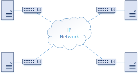
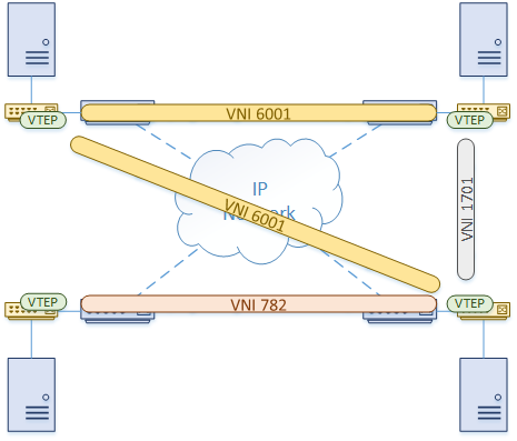
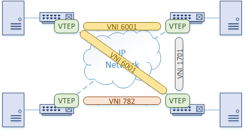
VxLAN separates the VNI from the physical network. This means no trunking across the infrastructure is needed. This is done by making each VNI a virtual overlay network. The core network, or underlay, runs at layer-3. VNI’s are layer-2 and run across the layer-3 network. To make this possible, VxLAN switches encapsulate layer-2 frames in layer-3 packets.
There are several advantages to this. As already mentioned, the core network does not have any layer-2 links. This means no trunking and no spanning-tree. Also, VNI’s can be stretched from one end of the network to another. This greatly simplifies mobility and allows hosts to have layer-2 adjacency.
Consider how this can help multitenancy. In an approach similar to MPLS, tenants can share a single infrastructure. Traffic is also limited to the VNI unless routed, so traffic can still be isolated. Depending on the configuration, VxLAN can also work with VRF’s for further isolation.
Now imagine a software-defined network. With the large address space, and decoupling the virtual network from the physical, it is simple to deploy new segments. It’s also easier to orchestrate the solution so customers can deploy their own networks.
One final benefit to mention is hardware support. While VxLAN can run well in software, some platforms implement VxLAN in hardware. The Nexus 9000-EX platform for example, implements VxLAN in the ASIC for better performance. If you’re still selecting switches, keep this in mind.
Overlays and Underlays
Key Concept
Traffic is encapsulated and sent over the IP network
VxLAN is an Overlay Technology. It’s called this because it creates virtual networks that are overlaid on a physical network. FabricPath and OTV are other examples of overlay networks.
The Underlay network is a physical IP network. This is also called the Transport Network. When a host sends traffic that belongs to a VNI, a VxLAN enabled switch encapsulates the traffic in UDP and IP headers. This is then sent across the underlay network, just like normal IP traffic. When the packet reaches the destination switch, the packet is decapsulated.
This makes the underlay and overlay networks independent. Changes can occur in the underlay without affecting the overlay. This also makes scaling easier, as routers can be added, removed, and upgraded, without needing to redesign the overlay network.
As you can see, the underlay network is really important. It needs to be stable, and tolerant to failure. There also needs to be plenty of bandwidth available. Any problems in the underlay will affect the overlay.
As the underlay is a routed network, it is managed by an IGP, like OSPF or EIGRP. It can also make good use of ECMP links for load sharing and near-instant failure recovery.
Key Concept
A Bridge Domain is a virtual network in the overlay
Each VNI is a separate virtual network, running in the overlay. Each of these networks represents a layer-2 network segment, called a Bridge Domain.
Spine/Leaf Topology
The Spine/Leaf Topology is commonly used in the IP underlay network. It’s quite different to the traditional hierarchy. Keep in mind that this is an architecture, and is not specific to VxLAN. Other technologies like FabricPath may also use spine/leaf.
This architecture uses two layers; the spine layer and the leaf layer.
The leaf layer is where hosts and other devices connect. The leaf layer handles all the VxLAN functions, like creating the virtual networks, and mapping VLANs to VNIs.
The spine layer is used for transport. The only thing that connects to spine switches is leaf switches. All links to the spine switches are routed links. This creates many ECMP paths, which can be managed by a routing protocol. The spine switches just pass traffic and are unaware that VxLAN even exists.
If you look at the topology diagram below, you will see that spine switches do not connect to each other. Leaf switches also do not connect to each other. This is to make the network consistent. This way everything is exactly two hops away. As all links are the same speed, and all destinations are two hops away, the network is very deterministic.
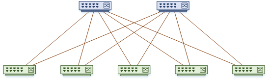
This type of network is often called a fabric. A fabric like this scales very well. If you need to add more hosts, you simply add more leaf switches. If you need more bandwidth, simply add more spines to the fabric.
When VxLAN is used in this architecture, the added benefit is that scaling the underlay network does not affect the overlay. There is no redesign required.
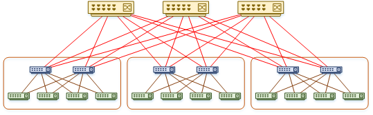
There may be cases where you manage a very large network. This may need to use several ‘pods’ of fabrics. These may benefit from a variation of this architecture, called a Super-Spine.
The super spine architecture adds an additional spine layer. The spines in each pod connect to the super spine as shown below.
Traffic Flow
Encapsulation and Decapsulation
As we have seen, VxLAN traffic is encapsulated before it is sent over the network. This creates stateless tunnels across the network, from the source switch to the destination switch.
Key Concept
VTEPs provide encapsulation and decapsulation services
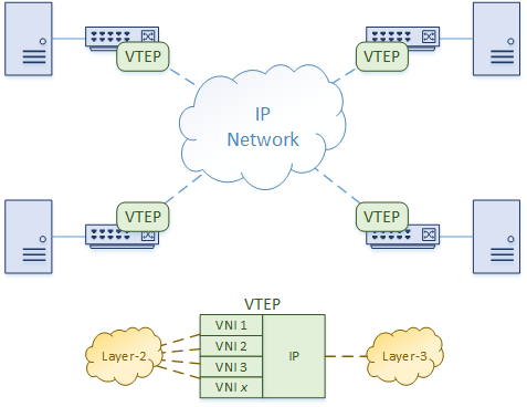
The encapsulation and decapsulation are handled by a component called a VTEP (VxLAN Tunnel End Point). In the Cisco Nexus platform, this is also called an NVE interface.
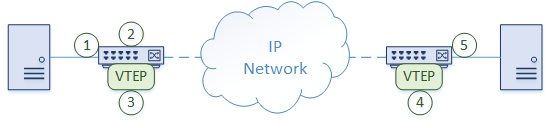
As shown in the diagram below, a VTEP has an IP address in the underlay network. It also has one or more VNI’s associated with it. When frames from one of these VNI’s arrives at the Ingress VTEP, the VTEP encapsulates it with UDP and IP headers.
The encapsulated packet is sent over the IP network to the Egress VTEP. When it arrives, the VTEP removes the IP and UDP headers, and delivers the frame as normal.
Hosts and Gateways
VxLAN is vendor-independent, so there are different ways it can be deployed. The two primary ways are Host Based and Gateway.
Hosts, such as a hypervisor, can have VxLAN configured on their virtual switches. Other devices, like firewalls and load-balancers, may also speak VxLAN natively.
In cases like this, there is no need to translate VLANs to VNI’s. Furthermore, the VTEPs are on the hosts themselves. The physical network infrastructure sees IP traffic, not VxLAN.
If the hosts do not support running VxLAN natively, or they just don’t use it, the switches can act as a VxLAN Gateway. Hosts belong to a VLAN. The switches map the VLAN to a VNI, and provide the VTEP functions.
In this model, the hosts are unaware of VxLAN, as the switches do all the work.
One advantage of this method is that VxLAN may (depending on platform) be implemented in hardware, providing performance benefits.
Of course, a combination of these two methods can be used. The switches can provide gateway services to some hosts, while other hosts speak VxLAN natively.
Bud Nodes
Sometimes in the VxLAN documentation, you will come across a term called Bud Node.
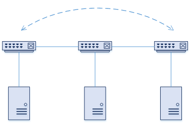
To put it simply, a Bud Node is a switch with a VTEP which is also used as a transit device for other VxLAN traffic.
Take the diagram below as an example. There are three switches, SW01, SW02, and SW03, which are all connected in-line. SW01 needs to send VxLAN traffic to SW03. SW02 needs to forward this traffic, but it shouldn’t perform any VxLAN related actions. In this scenario, SW02 is a Bud Node.
Not all platforms support Bud Nodes. Some platforms, like the Nexus 9000 series, use the hardware (ASIC) to make this possible.
Packet Walk
Let’s take a moment to see how traffic passes through a simple VxLAN network.
- A frame arrives on a switch port from a host. This port is a regular untagged (access) port, which assigns a VLAN to the traffic
- The switch determines that the frame needs to be forwarded to another location. The remote switch is connected by an IP network. It may be close or many hops away
- The VLAN is associated with a VNI, so a VxLAN header is applied. The VTEP encapsulates the traffic in UDP and IP headers. UDP port 4789 is used as the destination port. The traffic is sent over the IP network
- The remote switch receives the packet and decapsulates it. A regular layer-2 frame with a VLAN ID is left
- The switch selects an egress port to send the frame out. This is based on normal MAC lookups. The rest of the process is as normal
Interaction with vPC
vPC is a popular way to attach hosts to two switches for redundancy. So you may be wondering, how does vPC fit into this solution? How can we use vPC in a spine/leaf topology, if leaf switches don’t connect to each other?
Let me start with the spine/leaf topology. Although leaves are not supposed to connect to each other in a pure model, vPC gives us an exception. A pair of leaf switches still need to have a peer-link and a keep-alive link.
From the VxLAN perspective, there are a few tricky bits. Firstly, both switches have the same VTEP IP address. Well, sort of.
On a Nexus switch, the VTEP gets its IP address from a loopback interface. If vPC is used, each switch will have a different primary IP on the loopback interface. They will also have a secondary IP on the loopback, which is the same on both switches. The secondary IP is the anycast VTEP IP address.
As normal, the pair of switches still has separate control planes, meaning that they maintain their own set of peering, routing tables, and MAC tables.