
ASA Policy Based VPN
Introduction
This article will show how a policy based VPN can be configured between two ASA endpoints, across the internet, or some other network.
The type of VPN supported on the ASA is called a ‘policy-based VPN’. This is different to a route-based VPN, which is commonly found on IOS routers.
The main difference between policy-based and route-based is the way that VPN traffic is identified. In a route-based VPN, there is usually a virtual tunnel interface. Routes are put in place to direct traffic over the VPN tunnel using the tunnel interface. Routing works the same as with physical interfaces, so static routes or dynamic routing can be used.
Policy-based VPN is different as it does not have a virtual tunnel interface. Instead, it uses ACLs to identify interesting traffic, and passes that traffic over the VPN. This means that routing is not used to direct traffic.
ASA’s support Policy-Based VPN’s, and do not have tunnel interfaces.
There are some tricks to get the ASA to use routing over VPNs, but that is outside the scope of this article.
Starting Topology
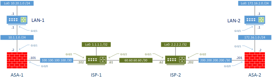
The topology below will be used for the VPN configuration. The green area represents the internet, and the blue area is our site 1 and 2. The red firewall is where the VPN configuration will take place.
ASA 9.5(2)204 and IOS 15.6 were used in my lab.
Initial Configuration
Each ISP router is configured to have an IP in a loopback interface to represent an internet address. This is important to confirm that the VPN config does not break regular internet access.
ISP default routes point to the alternate ISP router. Customer routes point back to the customer
LAN routers have an IP address to represent additional inside networks. Default route points to the ASA.
The ASA’s have the most complicated initial configuration. There are two interfaces, configured as inside and outside. For the lab, they’re configured to allow all traffic.
There is a NAT overload to allow internet access. The default route points to the ISP. Additional static routes point to the inside LAN networks.
The global policy has been editied to allow ICMP, and to allow the ASA to be visible in a traceroute.
Testing
As a quick test, we can ping the internet IP addresses to confirm access to the internet is up:
LAN-1#ping 1.1.1.1 source 10.20.1.1
Type escape sequence to abort.
Sending 5, 100-byte ICMP Echos to 1.1.1.1, timeout is 2 seconds:
!!!!!
Success rate is 100 percent (5/5), round-trip min/avg/max = 6/8/11 ms

LAN-1#ping 2.2.2.2 source 10.20.1.1
Type escape sequence to abort.
Sending 5, 100-byte ICMP Echos to 2.2.2.2, timeout is 2 seconds:
!!!!!
Success rate is 100 percent (5/5), round-trip min/avg/max = 7/12/19 ms

LAN-2#ping 1.1.1.1 source 172.16.2.1
Type escape sequence to abort.
Sending 5, 100-byte ICMP Echos to 1.1.1.1, timeout is 2 seconds:
!!!!!
Success rate is 100 percent (5/5), round-trip min/avg/max = 8/9/12 ms

LAN-2#ping 2.2.2.2 source 172.16.2.1
Type escape sequence to abort.
Sending 5, 100-byte ICMP Echos to 2.2.2.2, timeout is 2 seconds:
!!!!!
Success rate is 100 percent (5/5), round-trip min/avg/max = 6/7/8 ms
As expected, pinging from LAN to LAN does not work. This is what we aim to fix with the VPN configuration.
LAN-1#ping 172.16.2.1 source 10.20.1.1
Type escape sequence to abort.
Sending 5, 100-byte ICMP Echos to 172.16.2.1, timeout is 2 seconds:
Packet sent with a source address of 10.20.1.1
.....
Success rate is 0 percent (0/5)

LAN-2#ping 10.20.1.1 source 172.16.2.1
Type escape sequence to abort.
Sending 5, 100-byte ICMP Echos to 10.20.1.1, timeout is 2 seconds:
Packet sent with a source address of 172.16.2.1
.....
Success rate is 0 percent (0/5)
Configuration
The goal of this configuration is to allow traffic between the two LAN subnets, 10.20.1.0 and 172.16.2.1, to travel over the VPN. All other traffic, including internet access should remain the same.
It is recommended to understand the basics of IPSec before configuration. If you need a refresher, have a look at IPSec Basics.
To configure the VPN, we will be following these seven steps:
- Bypass NAT for VPN traffic
- Configure an IKEv1 Policy
- Create a Transform Set
- Create a Tunnel Group
- Configure an Access List to identify VPN traffic
- Create a Crypto Map to bind all the parts together
- Verify the configuration
The configuration takes place solely on the ASA’s.
The ASA’s have been configured with NAT overload for any traffic going from the inside to the outside. This needs to be bypassed for any local traffic with a destination of the remote LAN.
ASA-1 NAT Bypass
! Identify local and remote subnets
object network LOCAL_LAN
 subnet 10.20.1.0 255.255.255.0
object network REMOTE_LAN
 subnet 172.16.2.0 255.255.255.0

! Create a NAT 'bypass' rule
nat (inside,outside) source static LOCAL_LAN LOCAL_LAN destination static REMOTE_LAN REMOTE_LAN
ASA-2 NAT Bypass
object network LOCAL_LAN
 subnet 172.16.2.0 255.255.255.0
object network REMOTE_LAN
 subnet 10.20.1.0 255.255.255.0

nat (inside,outside) source static LOCAL_LAN LOCAL_LAN destination static REMOTE_LAN REMOTE_LAN
IKEv1 Policy
The IKE policy and transform set are configured identically on each server. These are used to provide encryption, authentication, and key sharing parameters.
The IKE policy is used in phase 1, where the initial tunnel is configured.
! Create policy
crypto ikev1 policy 1
 authentication pre-share
 encryption aes-256
 hash sha
 group 2
 lifetime 86400

! Enable policy on the outside interface
crypto ikev1 enable outside
Transform Set
The transform set is used to encrypt the tunnel created in phase 2.
crypto ipsec ikev1 transform-set VPN esp-aes-256 esp-sha-hmacASA-1 Tunnel Group
The tunnel group specifies the endpoints used in the VPN, as well as the preshared key for phase 1.
tunnel-group 200.200.200.201 type ipsec-l2l
tunnel-group 200.200.200.201 ipsec-attributes
 ikev1 pre-shared-key cisco
ASA-2 Tunnel Group
tunnel-group 100.100.100.101 type ipsec-l2l
tunnel-group 100.100.100.101 ipsec-attributes
 ikev1 pre-shared-key cisco
ASA-1 Access List
Access lists are created to identify interesting traffic; This is traffic that needs to travel across the VPN.
access-list LAN_Traffic extended permit ip 10.20.1.0 255.255.255.0 172.16.2.0 255.255.255.0ASA-2 Access List
access-list LAN_Traffic extended permit ip 172.16.2.0 255.255.255.0 10.20.1.0 255.255.255.0ASA-1 Crypto Map
The crypto map ties all the other parts together
! Create map
crypto map VPN 1 match address LAN_Traffic
crypto map VPN 1 set peer 200.200.200.201
crypto map VPN 1 set ikev1 transform-set VPN

! Apply to the outside interface
crypto map VPN interface outside
ASA-2 Crypto Map
crypto map VPN 1 match address LAN_Traffic
crypto map VPN 1 set peer 100.100.100.101
crypto map VPN 1 set ikev1 transform-set VPN
crypto map VPN interface outside
Verification
Finally, verify that the traffic can pass from one LAN to another.
LAN-1#ping 172.16.2.1 source 10.20.1.1
Type escape sequence to abort.
Sending 5, 100-byte ICMP Echos to 172.16.2.1, timeout is 2 seconds:
Packet sent with a source address of 10.20.1.1
!!!!!
Success rate is 100 percent (5/5), round-trip min/avg/max = 9/10/12 ms

LAN-2#ping 10.20.1.1 source 172.16.2.1
Type escape sequence to abort.
Sending 5, 100-byte ICMP Echos to 10.20.1.1, timeout is 2 seconds:
Packet sent with a source address of 172.16.2.1
!!!!!
Success rate is 100 percent (5/5), round-trip min/avg/max = 11/15/20 ms
The phase 1 SA’s can be verified:
ASA-1# Show crypto ikev1 sa

IKEv1 SAs:

   Active SA: 1
    Rekey SA: 0 (A tunnel will report 1 Active and 1 Rekey SA during rekey)
Total IKE SA: 1

1   IKE Peer: 200.200.200.201
    Type    : L2L             Role    : initiator
    Rekey   : no              State   : MM_ACTIVE
And phase 2 as well:
ASA-1# Show crypto ipsec sa summary

Current IPSec SA's:            Peak IPSec SA's:
IPSec            :     2         Peak Concurrent SA  :     2
IPSec over UDP   :     0         Peak Concurrent L2L :     2
IPSec over NAT-T :     0         Peak Concurrent RA  :     0
IPSec over TCP   :     0
IPSec VPN LB     :     0
Total            :     2
Note, the SA’s will only be created if traffic tries to use the VPN. If you try to view them before you ping, you will see that the VPN is not up:
ASA-1# Show crypto ikev1 sa

There are no IKEv1 SAs

ASA-1# Show crypto ipsec sa

There are no ipsec sas