
Route based VPN
Introduction
As discussed in the Policy Based VPN article, the ASA’s do not use tunnel interfaces for a site-to-site VPN. This causes problems if a dynamic routing protocol such as OSPF needs to run over the VPN. Under normal circumstances, it can’t.
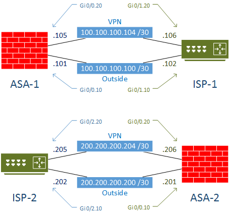
This article discusses a method of creating a VPN using subinterfaces. The physical interface that would normally be the outside interface is broken into two sub-interfaces with different VLANs. One of these sub-interfaces becomes the new ‘outside’ interface, and the other is the ‘vpn’ interface.
The VPN policies send VPN traffic over the VPN subinterface. The default route (for regular internet traffic) uses the outside interface.
By doing this, the VPN sub-interface provides a vague equivallence to having a tunnel interface, which allows dynamic routing protocols (with some tweaks) to run over the VPN.
This article will show how to configure this VPN, and get OSPF running across it.
Starting Topology
The topology below will be used for the VPN configuration. The green area represents the internet, and the blue area is our site 1 and 2. The red firewall is where the VPN configuration will take place.
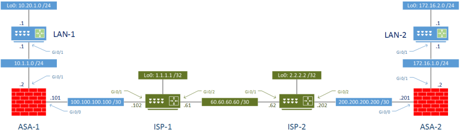
ASA 9.5(2)204 and IOS 15.6 were used in my lab.
This is similar to the topology used in Policy Based VPN, however there is a slight difference. The connection between the ASA’s and the ISP routers will use subinterfaces, in order to support routing over different interfaces.
The VPN subinterface is used for VPN traffic, while the Outside subinterface is used for normal internet traffic. In the real world, this would require configuring subinterfaces on the ISP routers. This may be impractical in some cases, such as if the ISP routers are managed by the ISP or a third-party. This would also be impractical if there is no onsite router, such as in the case of an unmanaged ethernet hand off in a data centre.
Initial Configuration
The LAN routers are configured with a loop back address to simulate LAN subnets. OSPF is used to dynamically share routes.
Testing
As a quick test, we can ping the internet IP addresses to confirm access to the internet is up:
LAN-1#ping 1.1.1.1 source 10.20.1.1
Type escape sequence to abort.
Sending 5, 100-byte ICMP Echos to 1.1.1.1, timeout is 2 seconds:
!!!!!
Success rate is 100 percent (5/5), round-trip min/avg/max = 6/8/11 ms

LAN-1#ping 2.2.2.2 source 10.20.1.1
Type escape sequence to abort.
Sending 5, 100-byte ICMP Echos to 2.2.2.2, timeout is 2 seconds:
!!!!!
Success rate is 100 percent (5/5), round-trip min/avg/max = 7/12/19 ms

LAN-2#ping 1.1.1.1 source 172.16.2.1
Type escape sequence to abort.
Sending 5, 100-byte ICMP Echos to 1.1.1.1, timeout is 2 seconds:
!!!!!
Success rate is 100 percent (5/5), round-trip min/avg/max = 8/9/12 ms

LAN-2#ping 2.2.2.2 source 172.16.2.1
Type escape sequence to abort.
Sending 5, 100-byte ICMP Echos to 2.2.2.2, timeout is 2 seconds:
!!!!!
Success rate is 100 percent (5/5), round-trip min/avg/max = 6/7/8 ms
As expected, pinging from LAN to LAN does not work. This is what we aim to fix with the VPN configuration.
LAN-1#ping 172.16.2.1 source 10.20.1.1
Type escape sequence to abort.
Sending 5, 100-byte ICMP Echos to 172.16.2.1, timeout is 2 seconds:
Packet sent with a source address of 10.20.1.1
.....
Success rate is 0 percent (0/5)

LAN-2#ping 10.20.1.1 source 172.16.2.1
Type escape sequence to abort.
Sending 5, 100-byte ICMP Echos to 10.20.1.1, timeout is 2 seconds:
Packet sent with a source address of 172.16.2.1
.....
Success rate is 0 percent (0/5)
Configuration
The ASA’s are going to be configured to create a VPN across the internet, on the vpn interfaces only. Internet access should be unaffected.
The VPN configuration is similar to the Policy Based VPN lab. It is also recommended to have a basic understanding of IPsec.
There are seven steps to configuration:
- Create ASA static routes
- Configure an IKE policy
- Create a transform set
- Create a tunnel group
- Identify traffic
- Create a Crypto Map
- Configure OSPF
The ASA’s are given static routes to reach the corresponding ASA’s VPN address. This is required to get the OSPF neighbours forming, so it can’t be done dynamically.
ASA-1
route vpn 200.200.200.206 255.255.255.255 100.100.100.106 1ASA-2
route vpn 100.100.100.105 255.255.255.255 200.200.200.205 1The IKE policy and transform set are configured identically on each server. These are used to provide encryption, authentication, and key sharing parameters.
The IKE policy is used in phase 1, where the initial tunnel is configured.
Notice that there is no need to bypass NAT, as there is in the Policy Based VPN lab. This is because the port overload NAT statement is applied to the outside interface, not the vpn interface. The VPN interface is routed.
IKEv1 Policy
crypto ikev1 policy 1
 authentication pre-share
 encryption aes-256
 hash sha
 group 2
 lifetime 86400

crypto ikev1 enable vpn
The transform set is used to encrypt the tunnel created in phase 2.
crypto ipsec ikev1 transform-set VPN esp-aes-256 esp-sha-hmacThe tunnel group specifies the endpoints used in the VPN, as well as the preshared key for phase 1.
ASA-1; Create a Tunnel Group
tunnel-group 200.200.200.206 type ipsec-l2l
tunnel-group 200.200.200.206 ipsec-attributes
 ikev1 pre-shared-key cisco
ASA-2; Create a Tunnel Group
tunnel-group 100.100.100.105 type ipsec-l2l
tunnel-group 100.100.100.105 ipsec-attributes
 ikev1 pre-shared-key cisco
Intersting traffic is usually identified here. However, this time it’s a little different. If traffic is directed over the vpn interface (which can be because of OSPF or static routing), all of that traffic is considered interesting.
Create an Access List
access-list VPN_Traffic extended permit ip any anyThe crypto map ties all the other VPN parts together
ASA-1; Create a Crypto Map
crypto map VPN 1 match address VPN_Traffic
crypto map VPN 1 set peer 200.200.200.206
crypto map VPN 1 set ikev1 transform-set VPN
crypto map VPN interface vpn
ASA-2; Create a Crypto Map
crypto map VPN 1 match address VPN_Traffic
crypto map VPN 1 set peer 100.100.100.105
crypto map VPN 1 set ikev1 transform-set VPN
crypto map VPN interface vpn
Finally, the OSPF configuration. The interfaces need to be configured as point-to-point, to avoid DR and BDR election.
The neighbours will not dynamically discover each other, so they need to be statically defined.
ASA-1; Configure OSPF
interface GigabitEthernet0/0.20
 ospf network point-to-point non-broadcast

router ospf 10
 network 100.100.100.104 255.255.255.252 area 0
 neighbor 200.200.200.206 interface vpn
ASA-2; Configure OSPF
interface GigabitEthernet0/0.20
 ospf network point-to-point non-broadcast

router ospf 10
 network 200.200.200.204 255.255.255.252 area 0
 neighbor 100.100.100.105 interface vpn
Verification
Firstly start by confirming that the internet IP’s are still accessible
LAN-1#ping 1.1.1.1 source 10.20.1.1
Type escape sequence to abort.
Sending 5, 100-byte ICMP Echos to 1.1.1.1, timeout is 2 seconds:
Packet sent with a source address of 10.20.1.1
!!!!!
Success rate is 100 percent (5/5), round-trip min/avg/max = 8/11/22 ms

LAN-2#ping 1.1.1.1 source 172.16.2.1
Type escape sequence to abort.
Sending 5, 100-byte ICMP Echos to 1.1.1.1, timeout is 2 seconds:
Packet sent with a source address of 172.16.2.1
!!!!!
Success rate is 80 percent (4/5), round-trip min/avg/max = 10/11/15 ms
Confirm VPN details
Phase 1 SA’s
ASA-1# Show crypto ikev1 sa

IKEv1 SAs:

   Active SA: 1
    Rekey SA: 0 (A tunnel will report 1 Active and 1 Rekey SA during rekey)
Total IKE SA: 1

1   IKE Peer: 200.200.200.206
    Type    : L2L             Role    : initiator
    Rekey   : no              State   : MM_ACTIVE
Phase 2 SA’s
ASA-1# Show crypto ipsec sa summary

Current IPSec SA's:            Peak IPSec SA's:
IPSec            :     2         Peak Concurrent SA  :     2
IPSec over UDP   :     0         Peak Concurrent L2L :     2
IPSec over NAT-T :     0         Peak Concurrent RA  :     0
IPSec over TCP   :     0
IPSec VPN LB     :     0
Total            :     2
Confirm that OSPF neighbours have formed.
ASA-1# show ospf neighbor
Neighbor ID     Pri   State           Dead Time   Address         Interface
200.200.200.206   0   FULL/  -        0:00:39    200.200.200.206 vpn
10.20.1.1         1   FULL/DR         0:00:34    10.1.1.1        inside

ASA-2# sh ospf neighbor
Neighbor ID     Pri   State           Dead Time   Address         Interface
100.100.100.105   0   FULL/  -        0:00:34    100.100.100.105 vpn
172.16.2.1        1   FULL/DR         0:00:39    172.16.1.1      inside
OSPF Routes are in the routing table.
ASA-1# sh route ospf
!!!
Gateway of last resort is 100.100.100.102 to network 0.0.0.0
O        10.20.1.1 255.255.255.255 [110/11] via 10.1.1.1, 00:07:24, inside
O        172.16.1.0 255.255.255.0 [110/20] via 200.200.200.206, 00:07:14, vpn
O        172.16.2.1 255.255.255.255            [110/21] via 200.200.200.206, 00:07:14, vpn
O        200.200.200.204 255.255.255.252            [110/20] via 200.200.200.206, 00:07:14, vpn

ASA-2# sh route ospf
!!!
Gateway of last resort is 200.200.200.202 to network 0.0.0.0
O        10.1.1.0 255.255.255.0 [110/20] via 100.100.100.105, 00:07:50, vpn
O        10.20.1.1 255.255.255.255 [110/21] via 100.100.100.105, 00:07:50, vpn
O        100.100.100.104 255.255.255.252            [110/20] via 100.100.100.105, 00:07:50, vpn
O        172.16.2.1 255.255.255.255 [110/11] via 172.16.1.1, 00:07:50, inside
Ping works from end to end.
LAN-1#ping 172.16.2.1 source 10.20.1.1
Type escape sequence to abort.
Sending 5, 100-byte ICMP Echos to 172.16.2.1, timeout is 2 seconds:
Packet sent with a source address of 10.20.1.1
!!!!!
Success rate is 100 percent (5/5), round-trip min/avg/max = 10/13/19 ms

LAN-2#ping 10.20.1.1 source 172.16.2.1
Type escape sequence to abort.
Sending 5, 100-byte ICMP Echos to 10.20.1.1, timeout is 2 seconds:
Packet sent with a source address of 172.16.2.1
!!!!!
Success rate is 100 percent (5/5), round-trip min/avg/max = 11/15/18 ms