ICMP Types
Last Updated: [last-modified] (UTC)
Types Summary
The 4-byte ICMP header contains an 8-bit type field, which defines the ICMP type. The type determines what the ICMP packet is used for. Depending on the type, the 8-bit code field may also be used, which contains additional information. If the type does not have any codes defined, the code field is set to zero.
For more general information on ICMP, see ICMP for IPv4.
Below is a table of all currently defined ICMP types. Note that some of these are IPv4 or IPv6 specific.
| Type | Description | Status |
|---|---|---|
| 0 | Echo Reply | |
| 1-2 | Unassigned | |
| 3 | Destination Unreachable | |
| 4 | Source Quench | Deprecated |
| 5 | Redirect | |
| 6 | Alternate Host Address | Deprecated |
| 7 | Unassigned | |
| 8 | Echo | |
| 9 | Router Advertisement | |
| 10 | Router Solicitation | |
| 11 | Time Exceeded | |
| 12 | Parameter Problem | |
| 13 | Timestamp | |
| 14 | Timestamp Reply | |
| 15 | Information Request | Deprecated |
| 16 | Information Reply | Deprecated |
| 17 | Address Mask Request | Deprecated |
| 18 | Address Mask Reply | Deprecated |
| 19-29 | Reserved | |
| 30 | Traceroute | Deprecated |
| 31 | Datagram Conversion Error | Deprecated |
| 32 | Mobile Host Redirect | Deprecated |
| 33 | IPv6 Where-Are-You | Deprecated |
| 34 | IPv6 I-Am-Here | Deprecated |
| 35 | Mobile Registration Request | Deprecated |
| 36 | Mobile Registration Reply | Deprecated |
| 37 | Domain Name Request | Deprecated |
| 38 | Domain Name Reply | Deprecated |
| 39 | SKIP | Deprecated |
| 40 | Photuris | |
| 41 | Experimental | |
| 42-252 | Unassigned | |
| 253-254 | Reserved |
Active Types
There are many types which have been deprecated, or are reserved for some reason. The ones that are still active are outlined here.
Echo and Echo-Reply
ICMP echo and echo-reply are commonly use in the ping application. This sends an ICMP echo to a host, which returns an ICMP echo-reply. If unsuccessful, the request will either time out, or a device along the path will reply with some type of ICMP error message.
An echo packet has type 8 set in the ICMP header, and the reply uses type zero. Neither have any codes defined, so the code field in the header is always set to zero.
The second four bytes of the header includes two 16-bit fields; The Identifier and the Sequence. These are used to match a particular echo with the echo-reply. These fields are used differently depending on implementation. For example, Linux sets a unique identifier for each process, while Windows uses a single identifier for all processes (the value is selected at boot time). Both Linux and Windows use an incrementing sequence value for each echo.
The data area of the packet is used for padding out to a particular size. The padding is usually made up of ASCII characters. When a host receives an echo packet, its echo-reply packet must use the same data payload as the original echo.
The size of the data area will vary, based on the MTU of the LAN, or based on manually specified sizes. By default, the packet has to fit into the MTU of the LAN that the source host is part of. However, keep in mind that this does not mean that the packet will definitley fit into the MTU size of all network segments along the path from source to destination. If it is too large, the packet will need to be fragmented.
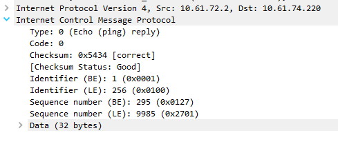
Below is an excerpt from a packet capture that was run during a successful ping. Notice that the type is set to zero, which is the echo-reply.

Destination Unreachable
Destination Unreachable messages are used to inform a sender that a packet could not be delivered to an endpoint. This message is sent unsollicited from the end host or an interim device, such as a router. In this context, unsolicited means that the source didn’t send an ICMP query and expect a response (such as with echo and echo-reply), another device simply informs the sender of the problem.
When this error is raised, a code is included (as shown in the table below), to give the sender a clue as to what is wrong. Additionally, the data field (after the full 8-byte header) includes a part of the original packet that failed. This is included so the sender can match the error to the process that generated the original packet.
| Code | Description | Notes |
|---|---|---|
| 0 | Net Unreachable | The network could not be found. May indicate a routing problem |
| 1 | Host Unreachable | The network was found, but the host was not. May be a routing problem, or the host is off |
| 2 | Protocol Unreachable | The specified protocol is invalid for this host |
| 3 | Port unreachable | The specified destination port is invalid for this host |
| 4 | Fragmentation Needed, and DF was set | The packet is larger than the MTU for the network, and the packet cannot be fragmented |
| 5 | Source route failed | Used if a source route is specified, but a router could not forward the packet |
| 6 | Destination network unknown | No longer used (Code 0 used instead) |
| 7 | Destination host unknown | Generated by a router local to the destination host. Indicates that the address is bad |
| 8 | Source host isolated | No longer used |
| 9 | Communication with destination network is administratively prohibited | The source device is not allowed to send to the destination network |
| 10 | Communication with destination host is administratively prohibited | The source can send to the destination network, but not the specified host |
| 11 | Destination network unreachable for type of service | The destination network cannot honour the value in the ToS field |
| 12 | Destination host unreachable for type of service | The destination host cannot honour the value in the ToS field |
| 13 | Communication administratively prohibited | Some sort of filtering is blocking the packet based on its content |
| 14 | Host precedence violation | Sent by the first-hop router. This happens if the precedence value in the ToS field is not allowed |
| 15 | Precedence cutoff in effect | Sent by a router if the precedence in the ToS field is lower than permitted for that network |
Generally, codes 0-5 seem to be the most common. Code 2 (protocol unreachable) and code 3 (port unreachable) are sent by the end host, and indicates that there is a problem on the host itself, such as port not open, process not running and so on.
Code 0 (Net Unreachable), code 1 (Host Unreachable), and code 5 (Source Route Failed) are sent by an interim router, and usually suggest that there is a routing or firewall problem.
Code 4 (Fragmentation needed and DF bit set) is also sent by an interim router. This happens if a packet is larger than the MTU for the interim network, however fragmentation into smaller packets is not allowed as the Dont Fragment bit in the IP header is set.
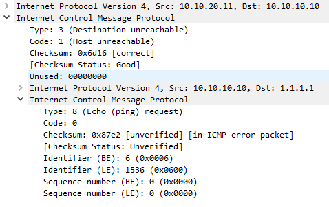
Below is a packet capture of an unreachable message. Notice that the type is set to 3 (Destination Unreachable), and in this case the code is 1 (Host Unreachable). Notice that the original packet (an ICMP Echo in this case) has been included in the data area of the ICMP message.
This error was generated when a host send a ping, but an interim router didn’t have a route to that host. Remember that the ICMP message will only be received if the interim router also has a route back to the source.

Redirect
An ICMP redirect message assists in making routing more efficient. In a case where a host has a default gateway, and the default gateway knows that a different local router if better for the network that the host is trying to reach, the gateway will send a redirect to the host, telling the host to use that router from now on. This may apply to all traffic to the particular destination network, or only traffic for the specific destination host.
It is important to understand that this helps with routing efficiency, but is not used to populate routing tables.
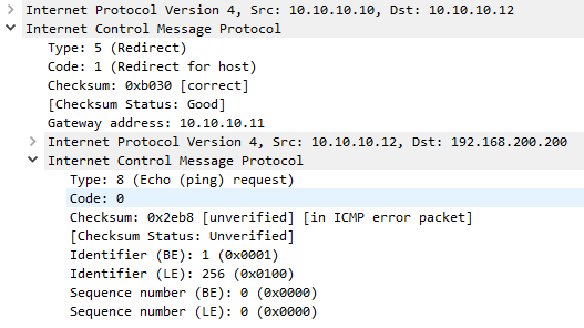
As shown in the packet capture below, the IP address of the ‘better’ router is included in the second 4 bytes of the header. The data section is populated with the first 8 bytes of the original packet, so the sender can match the message to the originating process.
| Code | Description | Notes |
|---|---|---|
| 0 | Redirect datagram for the network (or subnet) | Redirect future packets for all hosts on the destination network |
| 1 | Redirect datagram for the host | Redirect future packets for this host only |
| 2 | Redirect datagram for the type of service and network | No longer used |
| 3 | Redirect datagram for the type of service and host | No longer used |

Router Advertisement and Solicitation
The Router Solicitation and Router Advertisement messages are used as part of the Internet Router Discovery Protocol (IRDP), which is defined in RFC1256. This is a method for hosts to discover neighbouring routers without any manual configuring or DHCP support.
The Solicitation (type 10) message is sent by a host to multicast address 224.0.0.2, to request any routers on the local segment to identify themselves. Any routers that receive this message (and support IRDP) will reply with the Advertisement (type 9) message to announce their IP address as available for routing. Routers may also send the Advertisement message unsolicited on occasion (as more of an advertisement than a response).
If more than one router on the local segment responds, the host will pick the first response. If the host makes a poor choice, ICMP redirects will be used to make routing more efficient.
| Code | Description |
|---|---|
| 0 | Normal router advertisement |
| 16 | Does not route common traffic |
Time Exceeded
The time exceeded message can be generated for two different errors; One is that the TTL (Time To Live) field value in the IP header has decremented to zero, and the packet had to be dropped. The other is that a device could not reassemble a fragmented packed in the allocated time, and the packet was dropped. The code field is used to determine which one of these errors has been raised.
| Code | Description |
|---|---|
| 0 | Time to live exceeded in transit |
| 1 | Fragment reassembly time exceeded |
When a packet is sent from a source host, the TTL value in the IP header is set. Each layer-3 hop in the network will decrement this value by 1, and eventually the packet will either be delivered, or the TTL will drop to zero, and the packet will be discarded. This is done for loop prevention, so a packet will be dropped if it loops around for too long. When a router decrements the TTL to zero, it creates the Time Exceeded message, and sends it to the source host. Of course, this can be caused if the TTL is set too low in the first place.
This feature can be useful for security in some cases. For example, the BGP TTL Security feature will set the TTL so only routers within a maximum distance can be reached.
Be aware that some security devices, even though they are layer-3, do not decrement the TTL of packets passing through them.
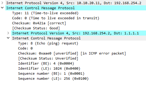
The packet capture below shows an example of the Time Exceeded message, due to the TTL expiring.

There are times that a packet has to be fragmented into smaller pieces. When the fragments arrive at the destination, they need to be reassembled into the original packet. The occasional problem here is that one of the fragments may go missing, resulting in the entire packet being discarded.
To handle this, the IP stack starts a timer when the first fragment arrives. If the timer expires before all the fragments are reassembled, the packet is discarded, and the Time Exceeded message is created and sent to the source.
Parameter Problem
The Parameter Problem message is a generic ‘catch-all’ message. that is used if no more specific error applies. This will also be used if there is a corruption or missing data in the IP header.
When the Parameter Problem message is sent, a pointer is included in the high 8-bits of the second part of the header. This pointer contains the location of the problem in the original packet.
In some cases, the pointer is not included. For example, if there is data missing (codes 1 and 2), there will be no pointer. After all, it’s difficult to point to data that is not there.
| Code | Description | Notes |
|---|---|---|
| 0 | Pointer indicates the error | Location of the error in the packet |
| 1 | Missing a required option | An option is missing from the IP header |
| 2 | Bad length | The length is incorrect, suggesting that the packet is missing data |
Timestamp-Request and Timestamp-Reply
Timestamps can be used to synchronise time between devices. To achieve this, a device sends a Type 13 Timestamp-Request to another device. In the request, it includes the time that the packet was sent, measured in milliseconds past midnight in Universal time. The second four bytes of the header include an identifier and sequence number which are used to match requests and replies.
In response, the recipient generates a type 14 Timestamp-Reply. The header format is the same as the request, but the payload includes the original timestamp, the timestamp when the packet was received, and the timestamp for when the reply packet was sent.
Photuris
Photuris is an application-layer session-key management protocol (RFC2522). It is used to generate session keys and establish IPSec SA’s. It uses ICMP to report on negotiation failures.
| Code | Description |
|---|---|
| 0 | Bad SPI |
| 1 | Authentication Failed |
| 2 | Decompression failed |
| 3 | Decryption failed |
| 4 | Need Authentication |
| 5 | Need Authorization |
References
Wikipedia – Ping (networking utility)
Firewall.cx – ICMP – ECHO / ECHO REPLY (PING) MESSAGE
Wikipedia – ICMP Router Discovery Protocol
Network Sorcery – ICMP type 10, Router solicitation
INACON – Photuris
The TCP/IP Guide – ICMP Version 4 (ICMPv4) Error Message Types and Formats