
EIGRP Design
EIGRP has a strength. It doesn’t need a strict topology like OSPF does. For this reason, it works well in unplanned topologies.
This strength is also its weakness. When you’re not forced to think about your topology, it’s easy to take shortcuts. As the topology grows, you may encounter scaling problems.
Think of a network that has grown to include a hundred routers. When a route is lost, EIGRP may send out a query message to its neighbours. Those routers flood this out too, and eventually, the route may be Stuck-in-Active (SIA).
In this article, we’ll have a look at how to scale EIGRP, how to limit queries, and how to improve convergence.
Query Messages
Key Design Point
Limit query propagation scope
If EIGRP loses a route, it needs to consider an alternate path. ECMP makes this easy. If the paths have the same cost, they’re all in use anyway, so there’s no need to go looking for an alternative. If that’s not an option, it will look for a feasible successor.
If there’s no ECMP and no feasible successor, EIGRP will send out a query. This is where EIGRP asks its neighbours ‘do you have a path to this route?’ If the neighbours do have a path, they will return the information to the router that sent the query.
What happens if a router receives a query, but it doesn’t have an alternate path? This router will send a query to its neighbours. If they don’t have a path, they will also forward the query to their neighbours, and so on.
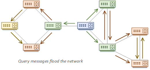
As you can see, this can end up in a query flood. If the topology grows too large, query propagation can break the network.
When an EIGRP router is waiting for a query response, the route status goes to Active. This means that that the router is actively looking for a path to the route. If the route is Stuck in Active for too long, the neighbour relationships are reset.
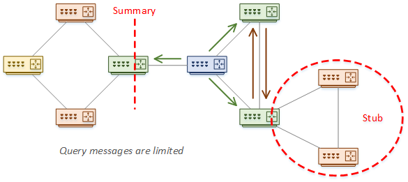
This brings us to the key design point. The scope of query propagation through the network should be limited.
Start by understanding the topology. For example, it is unlikely that a WAN site will have an alternate path to a campus route. So, in this case, a campus router should not send queries over the WAN.
In the following sections, we’ll have a look at how to limit queries, and how topologies can affect them.
Limiting Queries
Key Design Point
Use a good IP addressing scheme
There are several ways to prevent query flooding. The first one method is to use ECMP, or have a feasible successor. If the router already has an alternate path, it won’t send queries at all.
Stub routers are also great. A router will not send a query to a stub neighbour. This is where it’s important to understand your topology.
Also on the topic of topology, consider limiting the number of peer routers. The more peers, the more query messages. More peers may sound like a good thing on the surface, but there is a point where it overcomplicates the network. Understand your topology, and be honest about what you really need.
One of the best options is to summarise. This provides a natural boundary for queries. We’ll have a more detailed look at this soon.
The last option is using distribute-lists and route-maps. These filter routes when the IP addressing scheme does not allow good summarization. The point here is that not all routers need to know all routes. This is fewer routes to get stuck in active.
Sometimes, people like to use a Multiple-AS topology to limit queries. And on the surface, this sounds good. Queries are not sent between AS’s.
Consider what happens though, when sending a query to a router that is in both autonomous systems. This router creates its own queries and forwards them to its neighbours. As you can see, Multi-AS does not really limit queries, but it does increase complexity.
There are some valid reasons for Multi-AS, which we’ll have a look at later.
Summarization
Summarization is great for limiting query scope and routing table size. But this is not the kind of thing that you want the router to manage for you. Unless you have a good reason, disable auto-summarization. It is better to be deterministic, and manage your own summaries.
In some cases, you may need specific routes rather than a summary. This may be to prevent sub-optimal routing. In a case like this, you can still summarize. You can expose the more specific routes with a leak-map.
In a hierarchy, remember to only summarize north and south. Do not summarize between distribution switches.
Key Design Point
Manually assign a summary metric
When summarising routes, we may lose some metric information. The routers will look at the metrics of all the routes in the summary. They then include the best metric to advertise with the summary route. If the route with the best metric is lost, the summary metric will be recomputed.
To prevent changes in the summary metric, one option is to use a loopback interface. Give the interface an IP within the summary range, and advertise it into EIGRP. Hard-code the interface with the best metric. As the loopback interface will not go down, the router will always use its metric.
There is a catch with this method though. If all routes in the summary go down, the summary route should be removed from the routing table. But, loopback interfaces do not go down on their own. So, the summary route will remain, creating a black-hole.
A better option is to use the summary-metric command. This achieves the same goal, without the downside of the loopback interface.
Convergence and Neighbours
Detecting Neighbour Failures
EIGRP uses a series of timers to detect when neighbours fail. The hello timer can be as low as one second, with a hold timer of three seconds. If there are no hellos and the hold timer expires, the neighbour is down.
Cisco does not recommend using a hello timer of fewer than two seconds. This prevents neighbour drops if there’s a problem with hello messages and latency.
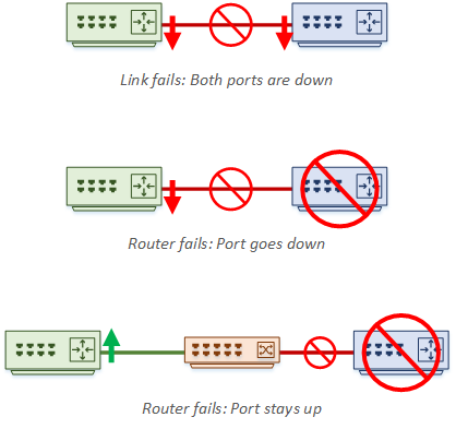
This can be surprising at first. After all, don’t we want sub-second convergence? Firstly, remember that the timers are not used to detect normal link failures. If a link fails, the port will go down and cause a routing event without needing a timer to expire. Also, if a directly connected neighbour dies, the port will also go down, which our router will detect.
Timers handle errors that the router can’t immediately see. For example, what if we connect routers through a switch? If Router-A dies, Router-B’s port will stay up, as the switch port is up. Also, consider media converters, or a software fault on the router itself. This is when we need timers.
But even so, isn’t this too long to wait for convergence? This is where BFD (Bi-Directional Forwarding) comes in. This is in the routing design article, but let me offer a quick summary here.
BFD is a separate protocol that has fast hellos. Hello timers are tunable down to 50ms. When BFD detects that a neighbour loss, it reports this to EIGRP, which can then mark the neighbour as down.
Fast Convergence
EIGRP can be very fast to converge. One reason for this is that it is a distance vector routing protocol. Unlike OSPF, it doesn’t have to build a logical topology of the entire network.
In fact, when tuned well, EIGRP can converge 1000 routes in about 120ms. If you have a large network, you may find a router with 10000 routes. This would take 1200ms to converge, which is too long. If you have a router like this, you need to take steps to decrease the size of the routing table.
For the best possible convergence, use ECMP. Also, make sure that routes have a Feasible Successor in place, ready to use. This will really help with convergence time as your routing table scales up.
To tune convergence even further, consider the IP Fast Reroute (IP-FRR) feature. This is based on feasible successors, but with a small difference.
Normally, an FS will not be in the routing table, or forwarding table (CEF). IP-FRR changes this by adding the FS as a ‘repair route’, under the valid route in the routing table. Once it’s in the routing table, it will also be entered into the CEF table.
The result of this is faster convergence, because the route is already in the route tables. Consider using this whenever you have a feasible successor. The small downside is that there is more load on the CPU.
The Graceful Restart (AKA, Non-Stop Forwarding) feature allows neighbours to be informed when EIGRP restarts. This allows a neighbour to have a grace period. It keeps the routes in the routing table while reestablishing relationships.
This is at odds with BFD. The goal of BFD is to detect failure quickly and route around them. The goal of Graceful Restart is to keep routes in place and route through a failure. Don’t try to use both features at the same time.
The best place to use Graceful Restart is with a pair of devices. For example, it would be useful between two distribution switches.
Topologies
EIGRP is really flexible. Unlike OSPF, there is no need for areas and no limit on where summarization can occur. That said, it’s still a good idea to think it out first.
We can logically divide EIGRP into tiers. This is like areas in OSPF, but it’s not as strict. These tiers are not defined in the config like an area. They are just a way for us to logically see the topology.
Tiers do not have to match the campus hierarchical design, but this will probably make it easier. You can use as many tiers as you want.
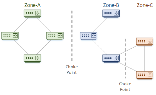
Consider the topology below as an example. This is broken into three tiers or Zones. Each zone is a failure domain. A failure within a zone should not affect any other zones.
Between the zones are Choke Points. These are aggregation points and are the logical places to use summarization. This shows the advantage to a good IP addressing scheme. This is also the place to apply filtering and other policies.
The topology depth is the number of hops from one end of the network to the other. In this example, the depth is six hops.
When using EIGRP within the campus, be careful in the core layer. Policies are good at choke points, but do this on the distribution side. The core should be as lightweight and simple as possible.
Campus Topology
The network topology influences where to place choke-points and zones. A well-designed campus makes this easier on us, as it will follow the hierarchical model.
The first decision to make here is, how many layers should we use? Often, two or three would be a good choice. This is influenced by the size of the network, geographic dispersal, topology depth, and so on.
To begin with, it’s recommended to have a topology diagram of your network.
A two-layer topology could be roughly based on the core and distribution layers. The core layer summarises south-bound toward the distribution layer. Likewise, the distribution layer summarises north-bound.
Avoid flooding routes through the core. Part of this means hiding edge networks behind summaries. Also, the core can use policies to define which routes it will accept. This prevents rogue routes from getting in.
Be careful to limit the number of policies in the core though, as the core needs to be lean and fast.
The three-layer model follows the hierarchical topology more closely. The principles of the two-layer design apply here as well. This design adds chokepoints between access and distribution layers.
Access layer switches represent the edge of the network. So, they should be considered to be stub networks. Access switches usually only connect north-bound to the distribution layer. In some cases, they will connect to each other as well. In these cases, remember to configure these links as passive interfaces. This reduces the number of peers in the access layer, which reduces query scope.
Summarisation happens between layers. Don’t summarise within layers, as this can introduce sub-optimal routing and black holes. Sometimes, you can use traffic engineering to direct traffic along better paths.
Hub and Spoke Topology
The hub-and-spoke topology is typically used in the WAN. In this topology, the hub provides an ideal choke point.
Spokes can be hub zones. They will only need the default route advertised to them. Sometimes, it may not be possible to send a default route to a spoke. As an alternative, summarize the routes as much as possible.
The hub routers will advertise a summary of the spoke back to the rest of the network. To prevent the spokes advertising rogue networks, consider route filtering.
Key Design Point
Do not summarise between hubs
For redundancy, there are often two hub routers. Sometimes this can lead to suboptimal routing.
Imagine a case like the one shown below. One hub router loses its link to the spoke router. The rest of the network will not know that the path is gone. Traffic may still arrive at this hub, which will then have to flow through the alternate hub router.
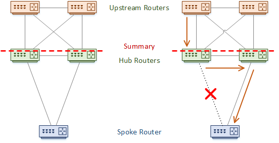
In a worse scenario, there is summarization between the two hubs. When the hub with the failed link receives traffic, it will not have a more specific route than the summary. The problem is that summary routes use the null0 interface as the next-hop, causing a black hole. The solution is to never summarise between the hub routers.
Key Design Point
Configure spokes as hubs
Spoke routers should not be transit routers. It makes no sense then, that query messages should travel over the WAN to the spoke routers. This is another good reason to configure them as stub routers.
Keep this in mind though. Stubs aren’t used to optimise routing. They optimise the routing table. Sometimes, you need a more specific route. If you need to do this, consider leaking routes with a leak-map.
An example of this is when there is a backdoor link between two spokes. A spoke will learn routes over the back door, but will not advertise them back to the hub. If the link between spoke and hub goes down, the back door link is not used by default. This is when to leak routes.
Scalability on the hub routers depends on the spoke link interfaces. If each spoke uses a separate interface, the processor becomes the limiting factor. If the spokes use a single interface, then queue congestion is the limiting factor.
From the EIGRP specific perspective, more spokes mean more neighbours. More neighbours mean slower convergence. Look out for a ‘tipping point’, where more hub routers would be beneficial.
Imagine a case where you have a service provider’s network between your hubs and spokes. I’m not thinking about dedicated layer-2 links or VPLS in this case. Rather, something like MPLS, where the provider adds extra layer-3 hops.
This causes problems for routing protocols, as neighbours need to be directly connected. One solution is to let the service provider take part in EIGRP with you. Often this is not the best option.
Another possibility is to use EIGRP OTP (Over the Top). This uses LISP packets to allow EIGRP neighbours to run over the top of the service provider network. Don’t panic though, you don’t actually need to configure LISP!
Autonomous System Scaling
When the network grows, one design is to break the network into two EIGRP Autonomous Systems. The theory behind this is to limit the scope of queries at the AS boundary and to help scalability.
But this is not a recommended design for these requirements. Redistribution adds complexity and introduces an increased risk of routing loops. Of course, there are methods to do this the right, but a misconfiguration is now far more damaging.
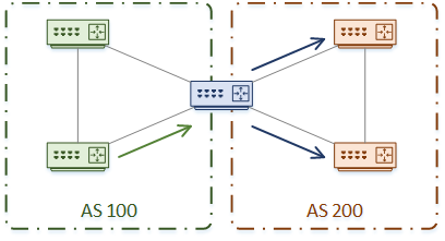
Now let’s think about queries. Are they really stopped at the AS boundary? Consider Router-A, which is on the boundary of AS100 and AS200. Router-A receives a query message from a router in AS100. It can’t answer the query itself, so it forwards the query to all its neighbours. This includes neighbours on AS 200.
There is also the problem of sub-optimal routing. If routes are in different Autonomous Systems, the router may not choose the best path.
When considering this design, think to yourself “Is this how I want to scale my network? Is there a better way to limit queries?”
Despite this, there are some valid reasons to use multiple Autonomous Systems. Here are a few:
- There is a merger or acquisition, and networks need to be joined
- There is a migration from one design to another
- Autonomous Systems are managed by different teams