
GRE Tunnels
Introduction
When you want to join two networks together, one option you may investigate is a tunnel. GRE, or Generic Routing Encapsulation, is one of the technologies that we use to build these tunnels.
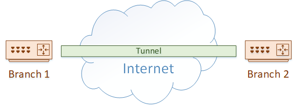
A great example of this is when you have two branch offices, which are separated by the internet. They may decide to build a GRE tunnel across the internet to provide connectivity.
GRE is not the only method of tunnelling, but it does have some advantages over some other technologies. For one, it is defined in RFC2784, so any vendor can support it. Also, it supports multicast packets, which means it can be used with dynamic routing protocols (unlike IPSec tunnels for example).
GRE is also lightweight, in that it does not have any built-in encryption, making it very easy to configure. If you need encryption, it’s not hard to add a layer of IPSec to the tunnel. This combines the advantages of GRE with the advantages of IPSec.
What are GRE Tunnels Used For?
Due to their versatility, GRE tunnels can be used for many different purposes. Connecting sites over the internet, as we just discussed, is one of the more obvious uses.
Another use is within the private network. You may have a case where there are many hops to travel over, but your IGP has a hop limit. RIP is an example of an IGP with this limitation. In this case, just build a tunnel across the network, and the IGP won’t see as many hops.
You may also have a case where you need to connect different ‘islands’ within your network. Perhaps you have business units or tenants that exist in different areas. GRE is a simple way to connect them. This also works during a migration to IPv6, where parts of your network have been migrated, and other parts have not.
A case that you may not have thought of is connecting to a DDoS service. If you use a provider like Akamai to mitigate DDoS attacks, you will connect to them with a GRE tunnel. Inbound traffic flows to them first, DDoS traffic is removed, and legitimate traffic is forwarded to your network over the tunnel.
A final advantage that we touched on earlier is carrying traffic types that may not be supported by the network. Think of a WAN network that does not support multicast. How do you configure dynamic routing? Simply configure GRE tunnels, which can carry multicast traffic, including dynamic routing.
How GRE Tunnels Work
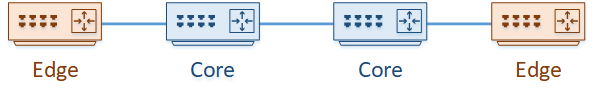
We’ll start with an example. We have a network of four routers. Two of these routers exist on the edge of the network, and two are in the core. Routing is configured so one edge router can reach through to the other.
We’ve decided that the edge routers need to communicate directly with each other, so they traffic they pass does not see the core routers.
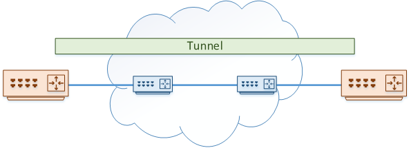
To achieve this, we’re going to use a GRE tunnel. Each edge router is configured with a Virtual Tunnel Interface (VTI). This is quite different to some other VPNs you may have seen (like the ASA), which use policies to tunnel traffic instead of using interfaces.
The VTI is configured with a destination address. This is the IP of the router at the other end of the tunnel. We’ll look at how this is configured soon.
The core routers are known as the underlay network. This is responsible for taking GRE packets and transporting them from one side of the network to the other.
The tunnel itself is the overlay network. Packets passing through the overlay network are unaware of the routers in the underlay.
Traffic that needs to pass from one edge router to the other is passed over the tunnel. To make this possible, each packet is encapsulated with two headers.
First, a GRE header is added. This includes information about the encapsulated data, such as the protocol used. For example, it may say that the payload is using IPv4.
Next, an outer IP header is added. This is used to deliver the encapsulated packets across the underlay network.
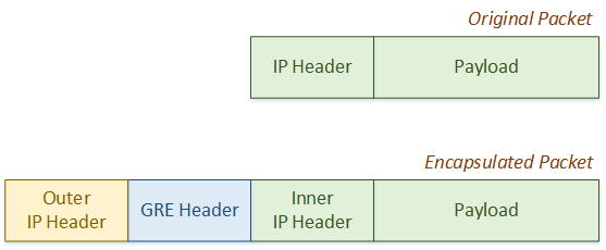
Thanks to the encapsulation process, the original payload and inner IP header is not changed by any hop in the underlay. This is why the underlay is invisible to any traffic in the overlay (in the tunnel). Normal routing transports traffic through the underlay.
Packet Walk
Let’s look at it from another perspective. In our example, two workstations need to communicate. The edge routers build the GRE tunnel across the core network.
The edge router on the left uses 10.10.10.10 as its ‘real’ IP address, while the edge router on the right uses 10.20.20.20.
They both use IP’s in the 192.168.1.0 network for the tunnel.
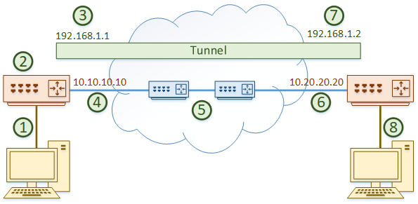
The packets follow these steps:
- The workstation on the left sends some data over the network. The packets arrive at the edge router
- The router looks at the routing table and determines that the tunnel interface has the best route to the destination, with 192.168.1.2 as the next hop
- The tunnel interface adds the GRE header, then the outer IP header. The outer IP header uses 10.10.10.10 as the source and 10.20.20.20 as the destination
- The encapsulated packet is forwarded out a real interface across the network
- The packet travels through the underlay. This behaves just like a normal packet travelling across the core
- The encapsulated packet arrives at the destination router, on the real interface
- The router sees that this is destined for the tunnel interface. The outer IP header and the GRE header are now removed
- The router forwards the decapsulated traffic to the destination workstation
When the workstation on the right replies, the process will be the same.
From the workstations perspective, it will not see the core routers. If you run a traceroute, you would see:
- The left edge router
- The tunnel IP of the right edge router
- The workstation on the right
Configuration
Time to have a look at how this is configured. We’re going to use Cisco IOS routers for our example.
The first step is to create the VTI with the interface tunnel 0 command. You can select any number you want for the tunnel interface. They are numbered simply because you may have more than one tunnel configured.
Next, we need to set the IP address of the tunnel interface. This is done just like a regular interface.
Remember how we add more headers to the packet? This will change the maximum packet size that can pass over the tunnel. The GRE header is 4 bytes, and the outer IP header is 20 bytes, so we need take the MTU of our real interface (commonly 1500), and subtract 24 bytes. This leaves us with an MTU of 1476.
Then, we want to adjust our MSS. This is used to help devices in the entire path to adjust their size to avoid fragmentation. This means that we subtract an additional 40 bytes, making the MSS 1436.
Also, take note that we’re not doing encryption in this example. If we do encryption (which we will discuss in another article), we will need to account for the IPSec headers as well.
Finally, we need to set the source IP or interface that is used when building the tunnel. This is the ‘real’ interface on the router.
The destination router’s IP also needs to be set.
interface tunnel 0
 ip address 192.168.1.1 255.255.255.0
 ip mtu 1476
 ip tcp adjust-mss 1436
 tunnel source 10.10.10.10
 tunnel destination 10.20.20.20
The corresponding config is done on the other router as well.
interface tunnel 0
 ip address 192.168.1.2 255.255.255.0
 ip mtu 1476
 ip tcp adjust-mss 1436
 tunnel source 10.20.20.20
 tunnel destination 10.10.10.10
Verification
Check that the tunnel interface is up.
Edge-1#show ip interface br
Interface                  IP-Address      OK? Method Status                Protocol
GigabitEthernet0/0         unassigned      YES unset  administratively down down
GigabitEthernet0/1         unassigned      YES unset  administratively down down
GigabitEthernet0/2         10.10.10.10     YES manual up                    up
Tunnel0                    192.168.1.1     YES manual up                    up
Confirm that the tunnel is in the local routing table.
Edge-1#show ip route
Gateway of last resort is 10.10.10.11 to network 0.0.0.0

S*    0.0.0.0/0 [1/0] via 10.10.10.11
      10.0.0.0/8 is variably subnetted, 2 subnets, 2 masks
C        10.10.10.0/24 is directly connected, GigabitEthernet0/2
L        10.10.10.10/32 is directly connected, GigabitEthernet0/2
      192.168.1.0/24 is variably subnetted, 2 subnets, 2 masks
C        192.168.1.0/24 is directly connected, Tunnel0
L        192.168.1.1/32 is directly connected, Tunnel0
And finally, confirm that we can ping across the tunnel.
Edge-1#ping 192.168.1.2
Type escape sequence to abort.
Sending 5, 100-byte ICMP Echos to 192.168.1.2, timeout is 2 seconds:
!!!!!
Success rate is 100 percent (5/5), round-trip min/avg/max = 4/5/7 ms
What’s Next?
Now the basic config is done, we can continue with any additional config that we may need. This may include:
- VRF configuration
- QoS configuration
- Dynamic routing
Remember that the tunnel interface behaves like any other interface. That means that you can apply any config to it that you would to a real interface.
Let’s take a quick look at dynamic routing to see it in action. Just configure simple OSPF commands on both the edge routers.
router ospf 10
 network 192.168.1.0 0.0.0.255 area 0
As you can see, OSPF comes up without any need to configure the core. The core is effectively transparent to OSPF in this case.
Edge-1#show ip ospf neighbor

Neighbor ID     Pri   State           Dead Time   Address         Interface
192.168.1.2       0   FULL/  -        00:00:36    192.168.1.2     Tunnel0