
Intelligent Traffic Director
ITD, An Overview
Intelligent Traffic Director (ITD) is a Cisco proprietary technology. It is capable of load balancing and traffic steering in the data centre. The Nexus N5K, N6K, N7K, and N9K switches offer ITD support. ITD needs the Enhanced Layer 2 or Network Services license.
As a load balancer, ITD is agnostic at a layer-3 or layer-4, to create server clusters. This concept also applies to network devices, to create firewall or IPS clusters.
ITD may replace several of the functions of a dedicated load balancer. There are still some things that a hardware load balancer is better suited for. For example, ITD cannot do SSL offloading.
For traffic steering, ITD may replace or supplement WCCP. This is especially useful for redirection to proxy servers, or WAN accelerators.
The Nexus platform has a major advantage over hardware load balancers. The data plane on the Nexus is capable of multi-terrabit throughput.
A single application server may have the throughput of 10G. ITD improves the application throughput, by spreading connections across a cluster of servers. This enables an application to scale up to 100’s of gigabits.
Features
ITD load balancing uses the Nexus ASICs. The result is high-performance, line-rate load balancing. Using the Nexus as the underlying platform also allows for vPC and VRF support. There is a need for the PBR feature though, which may come as an extra licensing cost.
ITD offers a high level of redundancy. N+M redundancy allows other nodes to take over the load of a failed node. This allows for more options than N+1 redundancy. Each node can have a different weight assigned, for granular traffic distribution.
Incoming traffic flows to the ITD VIP (Virtual IP), running on the switch. ITD then directs the connection to one of the servers in the cluster. There is support for ‘IP Stickiness’, or persistence. This means that the connection will continue to go to the same back-end server, as long as it’s up.
‘Bi-directional flow-coherency’ means that egress traffic will follow the same path as ingress traffic. This prevents problems with flow asymmetry.
ITD uses probes to determine if each of the servers in the cluster are up. Probes can be basic, such as an ICMP echo/reply, or a service-level check that looks at the TCP or UDP port.
For more ITD features, see the Cisco documentation.
Load Balancing
ITD may be a server or device load balancer. It may have a VIP assigned for incoming traffic, or it may listen for traffic on a particular interface. If a VIP is used, this is the IP client applications will use.
This is not a stateful load balancer. A stateful load balancer will track node state. They do this to make smarter decisions about how to allocate traffic to nodes. ITD is not a stateful load balancer
There are probes to determine the health of a server node. This is only to determine if the node is up.
Device groups define a collection of nodes, and assign health probes. A service is the ‘listener’ that receives traffic that needs to be load balanced. When using a VIP, it is configured at the service level.
When a connnection is initially seen by the load balancer, it is allocated into a bucket. A bucket is a group of connections, which gets allocated to a node. By default there is one bucket per node (for example, in a four node cluster, there are four buckets).
If you need more granular control, define more buckets per node. This is especially useful to handle failures. For example, a four node cluster may have 16 buckets (four per node). If one node fails, the four buckets can be more evenly distributed across the remaining nodes.
Unlike external load balancers, ITD services do not have advanced security features. This includes SSL offloading, binding certificates to the service, or header rewriting.
Deployment Modes
The three primary deployment topologies are:
- One Arm
- One Arm with vPC
- Sandwich
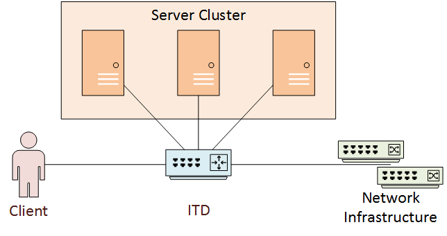
One Arm
In one arm mode deployment, the server cluster is not inline between the client and network. The ITD service needs to redirect traffic to the nodes.
This is called one-arm mode, as there is one interface into the server cluster network.
This mode helps to deploy clusters without needing to change the base network topology.
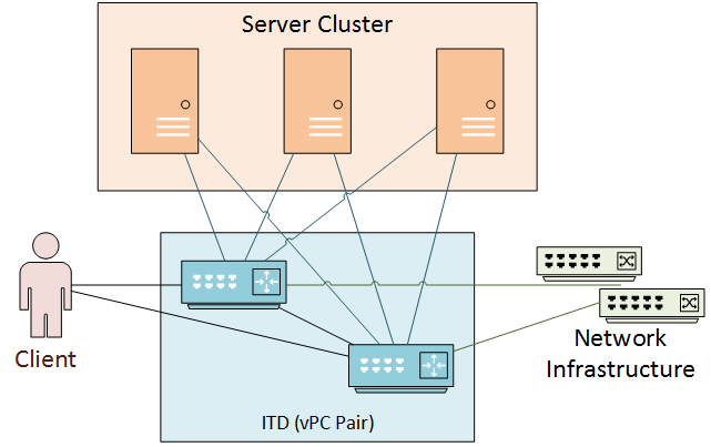
One-Arm + vPC
This deployment is like one-arm mode, but vPC makes it more resilient. The vPC network uses a pair of switches wth a peer-link between them.
ITD runs a single logical service across both switches. Each switch requires individual configuration, but the configuration must match exactly.
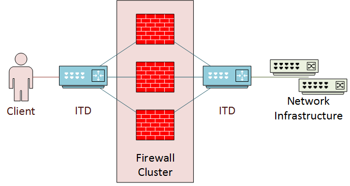
Sandwich
Sandwich mode has the cluster ‘sandwiched’ between two separate ITD services. This is also known as 2-Arm mode, as the cluster has two interfaces connecting to ITD. This is useful for firewall or IPS clusters. This puts the cluster inline between the client and back-end infrastructure.
This deployment looks a bit like a DMZ. It is also similar in that there is an ‘inside’ service and an ‘outside’ service.
Traffic symmetry is especially important in this design. Use source IP load balancing for incoming traffic on the ‘outside’ interface. Use destination IP load balancing for incoming traffic on the inside interface.
The two ITD services are separate, but use peer-synchronization. This means that both services have the same information about node health. Both are configured separately.
Basic Config
This section outlines a simple ITD deployment. This is for a basic two-node cluster, in a one-arm deployment.
Before beginning, be sure to install the appropriate licenses. Then, enable the ITD, PBR, and SLA Sender features.
feature itd
feature sla_sender
feature pbr
Configure a Device Group
A device group defines the nodes in the cluster. Each node can have a different weight, which affects the distribution of connections.
This example uses a simple ICMP probe. This checks once per minute to verify that the node is up. This means that there may be up to a minute between a server failing, and ITD knowing about it.
In production, tune the probes according the the needs of the application.
itd device-group Two-Node-Cluster
  node ip 10.0.0.1
  weight 10
  probe icmp frequency 60

  node ip 10.0.0.2
  weight 10
  probe icmp frequency 60
Configure a Service
In the example, we use a listening interface and a virtual IP address.
The load balancing method can be based around source or destination traffic. To get more granular an IP, or a combination of IP and port number, can be used.
The service also defines how to handle failures. There are three options:
- Node Reassign – When a node fails, its buckets are assigned to the first available node
- Node Least-Bucket – When a node fails, ITD reassigns the buckets to the node with the least buckets
- Bucket Distribute – Buckets are redistributed as evenly as possible across the active nodes
itd Two-Node-Service
  device-group Two-Node-Cluster
  ingress interface ethernet 1/1
  load-balance method src ip buckets 8
  virtual ip 172.16.0.1 255.255.255.255
  failaction bucket distribute
  no shutdown
Verification
Show itd and show itd brief are used to verify the configuration.
Switch# show itd brief

Legend:
 C-S(Config-State): A-Active,S-Standby,F-Failed
 ST(Status): ST-Standby,LF-Link Failed,PF-Probe Failed,PD-Peer Down,IA-Inactive

Name           LB Scheme  Interface  Status   Buckets
-------------- ---------- ---------- -------- --------
Two-Node-Servi src-ip     Eth1/1     ACTIVE   8

Exclude ACL
-------------------------------

Device Group                                       Probe  Port
-------------------------------------------------- ----- ------
Two-Node-Cluster

Virtual IP                              Netmask/Prefix Protocol     Port
------------------------------------------------------ ------------ ----------
172.16.0.1 / 255.255.255.255                           IP           0

Node  IP           C-S WGT Probe Port     Probe-IP   STS
------------------- -- --- ---- ----- --------------- --
1          10.0.0.1  A  10 ICMP                       PF
2          10.0.0.2  A  10 ICMP                       PF
If the status is showing as INACTIVE, show itd is a good place to start to get more information.
In this example, the status is INACTIVE because the interface that the service listens on (ingress interface) is down.
Switch# show itd

Legend:
 ST(Status): ST-Standby,LF-Link Failed,PF-Probe Failed,PD-Peer Down,IA-Inactive

Name           LB Scheme  Status   Buckets Reason
-------------- ---------- -------- ------- -------------------------------------
Two-Node-Servi src-ip     INACTIVE 8       Ingress Interface Down

Exclude ACL
-------------------------------

Device Group                                       Probe  Port
-------------------------------------------------- ----- ------
Two-Node-Cluster

Pool                           Interface    Status Track_id
------------------------------ ------------ ------ ---------
Two-Node-Service_itd_pool      Eth1/1       DOWN     1

Virtual IP                              Netmask/Prefix Protocol     Port
------------------------------------------------------ ------------ ----------
172.16.0.1 / 255.255.255.255                           IP           0

  Node  IP            Cfg-S   WGT Probe Port     Probe-IP   STS Trk# Sla_id
  ------------------- ------- --- ---- ----- --------------- -- --- -------
  1          10.0.0.1  Active  10 ICMP                       PF   2   10002

      Bucket List
      --------------------------------------------------------------------------
      Two-Node-Service_itd_vip_1_bucket_1, 3, 5, 7

  Node  IP            Cfg-S   WGT Probe Port     Probe-IP   STS Trk# Sla_id
  ------------------- ------- --- ---- ----- --------------- -- --- -------
  2          10.0.0.2  Active  10 ICMP                       PF   3   10003

      Bucket List
      --------------------------------------------------------------------------
      Two-Node-Service_itd_vip_1_bucket_2, 4, 6, 8