Introduction to IS-IS
Introduction
IS-IS, or Intermediate System to Intermediate System, is an open standard routing protocol. ISO published the standard as a way to route datagrams as part of their OSI stack. IETF later republished the standard, and added IP route support.
There are a lot of similarities between IS-IS and OSPF. For one, both are link state routing protocols, meaning that they both build a ‘map’ of the network. They both flood link state data through the network, and build a Link State Database (LSDB). Also, they both run Diikjastra’s algorithm on the LSDB to compute shortest paths.
So, if it’s like OSPF, why use it at all? Why not use OSPF instead? Well, there are two massive strengths to IS-IS. The first is it’s scalability. It’s much easier to build large networks with IS-IS than it is with OSPF. This makes it a common choice with service providers for their infrastructure.
The second strength is its agnostic approach to the data it carries. IS-IS carries a payload of reachability data, but for the most part it doesn’t care what’s in the payload. This is what makes it useful for protocols such as FabricPath. In contrast, OSPF carries IP routes only. When IPv6 came along, it required a whole new version of OSPF (OSPFv3) to carry the IPv6 routes. No such issue in IS-IS.
Components
As the history of IS-IS is in the OSI stack, some of the components are a bit different to what we’re used to in the TCP/IP world. Let’s clear up a few of the terms.
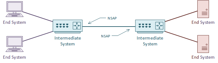
An IS is an Intermediate System. This is the ISO name for a router, and how IS-IS gets its name. It is communication between intermediate systems, or routers.
An ES is an End System. This is a device on the network, such as a server or workstation. In the original specification, an ES would take part in IS-IS. It would have no need for DHCP or FHRP, as it would already have a local routing table.
CLNS (Connection-Less Network Service) is a network service in the OSI stack. CLNP (Connection-Less Network Protocol) is the protocol that implements CLNS. If you’re more familiar with TCP/IP, this feels unusual. TCP/IP does not separate the service and the protocol in this way. This will make more sense with time.
An NSAP is a Network Service Access Point. This is a layer-3 address, for CLNS packets. This is like an IP address in the TCP/IP stack. IS-IS uses NSAP addresses for communication, not IP addresses. Again, this will make more sense as we go through the article.
TLV
TLV, or Type Length Value are the payload fields in IS-IS. The TLV fields carry routing information. IS-IS does not care what goes in these fields, which makes it protocol agnostic. This is a bit like shipping containers; The ship doesn’t care what’s in the containers.
IS-IS uses CLNS for transport. Each router has an NSAP address for sending and receiving link state information. The link state information may contain several TLV fields.
It is common to put IP routing information into the TLV’s. But any sort of data can be in there. It’s up to the receiving router to know what to do with the information.
Metric
Like OSPF, IS-IS uses cost as a metric. The specification says that this can be either a wide or narrow value. Cisco routers only support the wide metric. The narrow metric is not suitable for MPLS Traffic Engineering. The wide metric uses 24 bits for the link metric, and 32 bits for the path metric.
All links have a cost of 10 by default. This means that in a default implementation, hop-count forms the metric. It is up to the network designer to select a more suitable cost scheme.
Areas
Like OSPF, IS-IS uses areas. Areas can be either a backbone area, or normal area. To support this concept, a router may be one of the following types:
- Level 1 – A router in a normal area that does not connect to another area
- Level 1-2 – A router in a normal or backbone area that connects different areas
- Level 2 – A backbone router that does not connect to other areas
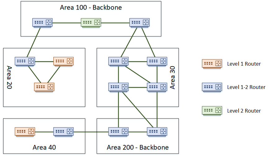
The topology below shows an example of a network with several areas.
There are a few interesting points in this topology. Notice that the backbone area is not restricted to being ‘area 0’ like in OSPF. In IS-IS, any area number can be the backbone. Also notice that it is possible to partition the backbone. In this topology, both area 100 and area 200 are the backbone.
A further point of interest is that area boundaries are not on the routers themselves. Rather the area boundaries are between routers. This is different to OSPF, where an ABR or ASBR router is the boundary.
Router Levels
Level 1 routers will only share routing information with other Level 1 routers. This makes them stub routers. In the topology above, area 40 is a stub area. Routing within an area is Level 1 Routing.
Level 2 routers will only share routing information with other level 2 routers. These routers track routing information between areas. This is Level 2 Routing.
Level 1-2 routers are special, as they take part in both level 1 and level 2 routing. They connect areas together, which makes them the perfect place to use summarization. These routers maintain a separate database for level 1 and level 2 routes.
Areas can connect to each other, or a dedicated backbone area could be used for transport. Backbones consist of routers that do level 2 routing, including level 1-2 routers. They won’t have hosts or Level 1 routers connected.
A small network does not need to have a backbone at all. It can start as a single area with only level 1 routers. As an alternative, it can be all level 1-2 routers, to make it easier to add a backbone later.
A domain is an entire IS-IS system under common administration. This is like the concept of an Autonomous System in BGP.
Inter-Area Routing
To route a packet outside an area, a level 1 router sends the packet to the nearest level 2 capable router. The nearest router is always used, regardless of the destination. Level 1 routers don’t have enough information about other areas to make a decision.
When the packet reaches the level 2 router, it gets forwarded across the backbone to get to the correct area. It is then passed on to a level 1 router in the area for local delivery.
To optimise routing, it is possible to leak routes from the level 2 database into the level 1 database. This technique prevents suboptimal routing outside the area. When leaking routes, they have a flag added. This prevents advertising them back into the level 2 database elsewhere.
When routing the packet within an area, the routers use the System-ID of the router for delivery. When routing packets between areas, the Area-ID is the address. These addresses are part of the NET Value.
NET Value
A Network Entity Title, or ‘NET’, is an address that identifies the router. It consists of the router’s system ID, and the area address. A NET is a type of NSAP address.
Each router’s NET is unique. They can be anywhere from 8 to 20 bytes long, but are often only 10 bytes.
An example of a NET is 49.0001.1720.1600.1001.00. As shown in the example below, this represents the Area-ID, System-ID, and NSEL values.
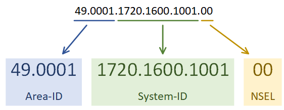
The address is a series of HEX values, separated by dots. The Area-ID is variable in length, but must be at least one byte. It is often a three-byte value. The first byte (49 in this example) is the AFI, or Address Family Identifier. This is often set to 49 for IS-IS, which is the OSI value for private addressing. 0001 in this example refers to area 1.
The System-ID needs to be unique within the area, but may overlap in different areas. Combining it with the Area-ID makes the entire address unique. In Cisco’s IS-IS implementation, the System-ID is 6 bytes.
The NSEL is the N-Selector. This has a special meaning in the OSI stack, but for IS-IS this will always be set to zero.
Adjacancies
IS-IS uses Protocol Data Units, or PDU’s to communicate. This is like a packet in OSPF terminology.
An IS-IS Hello PDU, or IIH, is like OSPF hello packets. Routers exchange IIH’s to form neighbour relationships, and share area addresses.
IS-IS sends IIH PDU’s at layer-2, using a multicast MAC address. This is why there is only a need for a single address (the NET or NSAP) per router. Addresses aren’t required per interface. This also shows that IP addresses on interfaces are irrelevant to IS-IS.
Level 1 routers need the Area-ID to match. Additionally, level 2 routers will ignore IIH’s from Level 1 routers. Authentication and network type must also match for neighbours to form.
Level 2 and Level 1-2 routers do not need level 2 IIH’s to have the same Area-ID
A Link State PDU, or LSP, contains routing information, and is flooded to neighbours. LSP’s are like OSPF’s LSA’s. There are two types of LSP’s; Level 1 LSP’s and Level 2 LSP’s. Level 1-2 routers send and receive both types.
The LSP contains a header and TLV fields. The TLV fields contain the information that is being advertised, such as IP routes. Extra TLV’s contain other data, like neighbour information, and authentication information.
When there are network changes, the router floods LSP’s out. Other routers receive these LSPs, and used them to build their Link State Database (LSDB). IS-IS is more efficient at this than OSPF. It combines several networks into an LSP, rather than sending many small LSA’s. This adds to the scalability of IS-IS, as more routers can exist on the network without over flooding.
When IS-IS is on broadcast media, one router is the Designated Intermediate System, or DIS. The DIS will flood LSP’s out, instead of having all routers flood the segment. This is like the Designated Router in OSPF.
Routers hold an election to select the DIS. The router with the highest priority on the segment wins the election and becomes the DIS. If there is a tie, the router with the highest MAC wins. DIS uses preemption, so if a router with a better priority comes along, it will become the new DIS.
There is no backup DIS. This is different to OSPF, which has a BDR role.
Configuration
In this lab we will configure IS-IS to carry IP routes. The router R2 will summarise the IP’s of the loopback interfaces into a /22 network.
The topology is as follows:
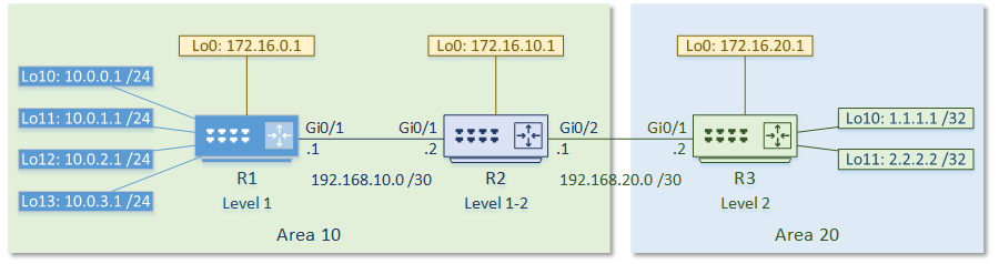
The first step is to enable the IS-IS process. Each IS-IS area uses a separete process. In the example below, the System-ID uses the IP address of Loopback 0 in the NET value. This could be any value, but reformatting a loopback IP makes troubleshooting easier.
The use of passive-interface is the same as with any other routing protocol.
The first IS-IS process on Cisco routers are set to Level 1-2. All later processes are Level 1 by default. Change this with the is-type command.
Following this, enable IS-IS on an interface.
Show clns neighbours confirms that neighbour relationships have been established.
Show isis database shows the LSDB. This is router reachability information.
Show clns interface shows the IS-IS settings for the interface.
We can see that IS-IS has learned routes, and installed them into the routing table.
Under the IS-IS process, a summary address can be configured.
If a default route were required, it could be advertised with default-information originate.
R2(config)#router isis
R2(config-router)#summary-address 10.0.0.0 255.255.252.0 level-2
You can see that R3 is now learning the summary address, rather than each individual network.
R3#show ip route isis
Gateway of last resort is not set

      10.0.0.0/22 is subnetted, 1 subnets
i L2     10.0.0.0 [115/20] via 192.168.20.1, 00:03:15, GigabitEthernet0/1
      172.16.0.0/32 is subnetted, 3 subnets
i L2     172.16.0.1 [115/20] via 192.168.20.1, 00:19:51, GigabitEthernet0/1
i L2     172.16.10.1 [115/10] via 192.168.20.1, 00:19:51, GigabitEthernet0/1
      192.168.10.0/30 is subnetted, 1 subnets
i L2     192.168.10.0 [115/20] via 192.168.20.1, 00:19:51, GigabitEthernet0/1