
Q-in-Q (Dot1q) Tunnelling
Stacking VLANs
Separating traffic by VLAN is nothing new. It may be separate departments, to provide boundaries, for security, or for a thousand other reasons.
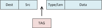
The Tagged, Untagged, and Native VLANs article introduces how VLAN tags work. As shown below, a frame has a VLAN tag inserted to identify the VLAN it belongs to.
Service Providers need to keep customer traffic separated. There are different ways to achieve this, depending on the provider link type. To achieve this at layer 2, we can use Q-in-Q tagging to insert an extra VLAN tag. This results in VLAN tags being ‘stacked’ in the frame.
The result is a frame with two tags; the customer tag (AKA, the C-TAG) and the service-provider tag (AKA, S-TAG):
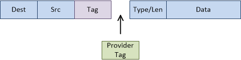
This can be called VLAN stacking, Q-in-Q tunnels, or dot1q tunnels. The ‘Q-in-Q’ comes from the 802.1Q VLAN specification.
Q-in-Q also helps providers to save money. When a provider gets a new customer, they have to provide a port into their core or aggregation network. These ports are likely to be 1Gbps, but the provider may be selling only 10Mbps services. The result is a waste of bandwidth. Instead, the provider could have an edge switch connected to the core port. Then, 100 10M customers could connect to the core port, separated by VLANs.
Another use for Q-in-Q is for a provider to pass traffic over an upstream provider’s network. For example, a small provider may have networks on the east and west coasts of a country. An upstream provider can bridge these two networks. Q-in-Q allows the smaller provider to pass layer-2 traffic over the intermediate provider.
Although usually associated with providers, enterprises may have a use for tunnels as well. Some examples include mergers between different companies with overlapping VLANs, or converging separate offices. One use case that’s becoming more popular is when connecting to the public cloud. If you want to connect a data centre to Azure or AWS, you will need a service provider. They provide the physical links, which would usually be deployed at layer-2. The links can be trunked, or they will likely offer you the option of running Q-in-Q.
Configuration
To test this out, we’ll use the topology below. There’s no special config on the routers. They are just there as a place to ping from. They’re basically simulating hosts.
The Edge switches also use a standard config. The ports facing the routers are access ports. The ports facing the ISP equipment are trunk ports.
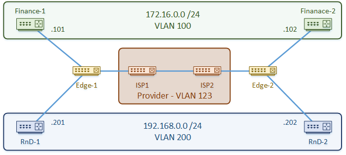
The configuration is quite simple. We’re using VLAN 123 as the S-TAG, so we start by defining that. We don’t need to define the customer VLANs on the ISP switches.
The link between the ISP’s is a normal trunk link. This has a slightly larger MTU to account for the extra VLAN tag.
The customer-facing port uses the S-TAG as the access VLAN. The switchport mode is set to dot1q-tunnel. When traffic arrives on this port, an extra VLAN tag is added, even if there is already one there.
Example – ISP1
vlan 123
 name S-TAG

interface GigabitEthernet0/1
 description ** To ISP2 **
 switchport trunk encapsulation dot1q
 switchport mode trunk
 mtu 1504

interface GigabitEthernet0/3
 description ** To Customer **
 switchport access vlan 123
 switchport mode dot1q-tunnel
Example – ISP2
vlan 123
 name S-TAG

interface GigabitEthernet0/1
 description ** To ISP1 **
 switchport trunk encapsulation dot1q
 switchport mode trunk
 mtu 1504

interface GigabitEthernet0/3
 description ** To Customer **
 switchport access vlan 123
 switchport mode dot1q-tunnel
 l2protocol-tunnel cdp
 l2protocol-tunnel stp
Three things must match between ISP1 and ISP2:
- S-TAG VLAN — mismatched VLANs place customer traffic in the wrong broadcast domain
- MTU on the inter-switch trunk — even one side at 1500 will silently drop large frames
- L2 protocol tunnelling — if one side tunnels CDP and the other doesn’t, protocol traffic won’t pass end-to-end
But what about traffic that normally uses the native VLAN? CDP and STP for example?
These can be tunnelled across the network with a few simple commands
STP and CDP Tunneling
interface GigabitEthernet0/3
 l2protocol-tunnel cdp
 l2protocol-tunnel stp
MTU Considerations
Q-in-Q adds a second 4-byte 802.1Q tag to every frame. A standard Ethernet frame has a maximum size (MTU) of 1500 bytes. With the extra tag, a full-size frame needs 1504 bytes to cross the ISP trunk — if the MTU isn’t increased, large frames are silently dropped.
The symptom is usually intermittent: small pings succeed while large transfers or application sessions fail. This is one of the most common Q-in-Q pitfalls.
The fix is to raise the MTU on the ISP-to-ISP trunk link. The customer-facing ports don’t need changing — the extra tag is added and removed by the ISP switches, so customers never see it.
interface GigabitEthernet0/1
 description ** To ISP2 **
 mtu 1504
Confirm the MTU is set correctly:
ISP1#show interfaces gi0/1 | include MTU
  MTU 1504 bytes, BW 1000000 Kbit/sec, DLY 10 usec,
To test whether MTU is the problem, ping with the df-bit flag and a large payload. If a large ping fails while a small one succeeds, MTU is the culprit:
ISP1#ping 172.16.0.1 size 1500 df-bitNote: If the customer is also running Q-in-Q on their side (triple tagging), the ISP trunk MTU needs to be 1508. Many providers configure jumbo frames (9000 bytes) on inter-switch links to avoid managing this case-by-case.
Verification
Find interfaces configured with Q-in-Q
ISP1#show dot1q-tunnel

dot1q-tunnel mode LAN Port(s)
-----------------------------
Gi0/3
Check the interface mode and S-Tag
ISP1#show interfaces gi 0/3 switchport | include Mode
Administrative Mode: tunnel
Operational Mode: tunnel
Access Mode VLAN: 123 (VLAN0123)
Trunking Native Mode VLAN: 1 (default)
Capture Mode Disabled
See which protocols are tunnelled
ISP1#show l2protocol summary
COS for Encapsulated Packets: 5
Drop Threshold for Encapsulated Packets: 0

Port                Protocol           Shutdown              Drop                  Status
                                       Threshold             Threshold
                   (cdp/lldp/stp/vtp)(cdp/lldp/stp/vtp)    (cdp/lldp/stp/vtp)
                   (pagp/lacp/udld)  (pagp/lacp/udld)      (pagp/lacp/udld)
------------------- ----------------  --------------------- --------------------- -----------
Gi0/3               cdp ---- stp ---  ----/----/----/----   ----/----/----/----   up
                    ---- ---- ----    ----/----/----        ----/----/----
Confirm end-to-end connectivity
CustA-Rtr1#ping 172.16.0.102
Type escape sequence to abort.
Sending 5, 100-byte ICMP Echos to 172.16.0.102, timeout is 2 seconds:
!!!!!
Success rate is 100 percent (5/5), round-trip min/avg/max = 9/9/11 ms
Troubleshooting
Traffic not passing at all
Confirm the customer-facing port is in tunnel mode. A common mistake is leaving it as a regular access port:
ISP1#show interfaces gi0/3 switchport | include Mode
Administrative Mode: tunnel
Operational Mode: tunnel
If it shows access instead of tunnel, the switchport mode dot1q-tunnel command was not applied. Also confirm the S-TAG VLAN exists in the VLAN database:
ISP1#show vlan id 123

VLAN Name                             Status    Ports
---- -------------------------------- --------- -------------------------------
123  S-TAG                            active    Gi0/3
Large frames dropping / intermittent connectivity
If small pings work but large transfers fail, the inter-switch trunk MTU is too low. Test with a large df-bit ping:
ISP1#ping 172.16.0.102 size 1500 df-bitIf this fails, check the trunk interface MTU and raise it to 1504:
ISP1#show interfaces gi0/1 | include MTU
  MTU 1500 bytes, ...
CDP/STP not tunnelling end-to-end
Verify which protocols are configured for tunnelling on the customer-facing port:
ISP1#show l2protocol summaryIf CDP or STP are missing, add them to the customer port:
interface GigabitEthernet0/3
 l2protocol-tunnel cdp
 l2protocol-tunnel stp
Customer VLAN traffic leaking between customers
Each customer must have a unique S-TAG VLAN. If two customers share the same S-TAG, their traffic is in the same broadcast domain on the ISP network. Audit the VLAN assignments:
ISP1#show dot1q-tunnel
ISP1#show vlan brief
Ensure no two customer-facing ports share an S-TAG unless that is intentional.