
Routing Design
For good scalability, you need a good design. This includes routing table sizes, convergence times, and failure detection.
In this article, we’ll have a look at some principles to improve routing. We won’t focus on specific routing protocols here, but take a more general approach.
Peering
Design Principle
Use passive interfaces by default
In the campus, take care when peering. Distribution switch pairs should peer with each other over a direct link.
Distribution switches will see layer-2 access switches as a path to peer on. By default, neighbour relationships will form across these switches.
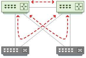
The best practice, in this case, is to prevent sending hellos through the access switches. To do this, set all interfaces as passive by default.
Design Principle
Whenever possible, use physical interface for peering
It’s common to use a lot of SVI’s in the data centre. This usually results in neighbours forming relationships over each SVI. The result, at best, is that this is messy and difficult to troubleshoot. At worst, poor tuning could result in a suboptimal path. The same principle as the campus applies here. Use passive interfaces by default, and select interfaces for peering.
Also on that topic, should we use SVI’s for peering at all? Newer recommendations suggest that, no, we shouldn’t.
SVI’s have a feature called Auto State. This allows the SVI to stay up if there are active interfaces in the VLAN. To do this, the switch scans interfaces for their state before taking the SVI down.
Think about the process:
- A link goes down
- The physical interface is marked as down
- Autostate scans other interfaces to see if the VLAN is up anywhere else
- When it can’t find any, the SVI is marked as down
- The routing protocol is notified
Link loss detection takes an extra 150-200ms, increasing convergence time. Consider the process when a using a physical interface for peering:
- The link goes down
- The interface is marked as down
- The routing protocol is notified
The entire process for a physical interface takes about 8ms. In short, use physical interfaces for peering whenever you can.
Convergence
Convergence is when there is a change in the environment, and the network adapts to it. From the point of view of a routing protocol, we’re interested in failure recovery. This could be a link going up and down, or a dead router. The goal is to lower the convergence time as far as reasonably possible.
There are four steps to convergence:
- Detect the event
- Propagate the event
- Process the event
- Update routing and forwarding tables
Detecting the event is noticing that a link or device has changed state. As already discussed, physical ports are best in this case.
It’s often misunderstood how the hello timers affect convergence. Hello timers detect neighbour failures, not ports going up and down. When a port goes up or down, the router knows this immediately. After all, it can ‘see’ its own port go down.
If a router fails, the link may not go down. This can happen, for example, if there is a switch or media converter between the routers. This is where the timers come into play. When the timers expire, a router will know that its neighbour is down.
Event propagation and processing is specific to the routing protocol. At a high level, the router will send updates to its neighbours to inform them of the event.
Each router adds this information into their data structures and processes them. OSPF, for example, updates the OSPF database and runs the SPF algorithm to find the best paths.
After finding the best paths, the router updates the routing and CEF tables.
BiDirectional Forwarding Detection
BFD is an independent protocol that has its own hello packets. It can detect a failure in as little as 50ms, making it a great alternative to built-in timers.
Larger platforms support BFD, and it is more popular in the carrier space. Each peer is aware of the other, and they are capable of negotiating timers. BFD pulls neighbour information from the routing protocol.
This is a protocol used to detect failures quickly. But that’s the limit of its function. It detects failures. When a failure occurs, BFD notifies the routing protocol. The routing protocol will then take the appropriate action.
Squares vs Triangles
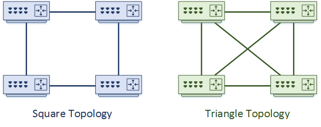
Routing topologies usually include redundancy. But how much do you need? Consider a case with four routers. As a general rule, they can be connected in a ‘square’ or ‘triangle’ topology.
Design Principle
If possible, use triangles not squares
The Triangle topology shown here is fully meshed. Every router has a direct link to every other router, as well as two alternate paths. This provides the most redundancy, as well as the potential for ECMP links. This is useful between access and distribution, to prevent using the access switches for transit.
Use the triangle topology when possible.
In a single site, triangle topologies are usually not too expensive. This starts to change when WAN links and separate buildings come into the picture. Imagine the cost of fully-meshing a few data centres together.
Sometimes, you’ll need square topologies. This may prevent using ECMP links, and result in a longer convergence time.
Summarisation
Design Principle
Use summarisation wherever possible to limit routes in the core
A routing tip that you will hear again and again, is to summarise whenever possible. There are several benefits, including smaller routing tables, and fewer updates. In the case of EIGRP, it provides query boundaries.
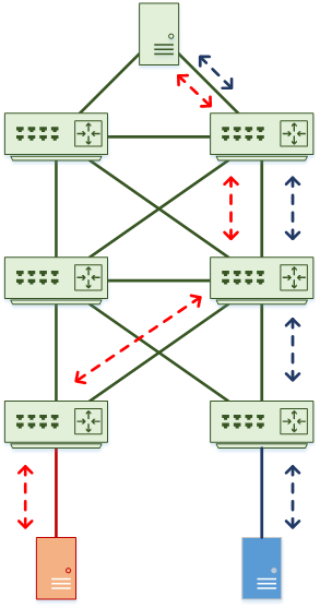
In practice, this means summarising at the access layer, towards the distribution layer. This prevents updates flooding into the distribution when links flap, or switches reboot.
In turn, the distribution layer summarises towards the core. The goal here is to protect the core from routing updates. If a route changes, the core won’t see it as long as the summary is in place. Make sure that there is a direct link between distribution pairs. This prevents peering across the core or access layers. Missing this can lead to routing black holes.
So, how far should you summarise? If you can, summarise right down to a default route. Use stub areas if you can.
There are some other benefits to summarisation. NAT, for one, is simpler when there are a contiguous block of addresses, rather than scattered ones. ACL’s are also simpler for the same reason.
CEF Polarization
It can be tempting to tune ECMP algorithms on all switches in the hierarchy. But, there is a side effect of doing this, called CEF Polarization.
Imagine a case where there are ‘left’ and ‘right’ uplinks on each switch in each tier. Each switch needs to decide which uplink to use for each traffic flow. Remember that ECMP uses algorithms to select links, just like etherchannel does.
Design Principle
Prevent CEF polarization. Tune the Distribution, not the Core.
If you use the same algorithms all the way up the tiers, all the switches will make the same decisions. The problem with this is that traffic gets pinned to the same uplinks across each tier.
The problem with this is that one set of uplinks may be over utilised, and the other set is unused. This is CEF polarization.
The recommendation is to leave the algorithms as default unless they’re not suitable. If you do need to tune, tune the distribution layer, not the core.
Routing Migration
Sometimes, you may want or need to migrate from one routing protocol to another. This can happen after a merger, or when you find RIP running in your network.
One common way to do this is to through redistribution. But beware. If this is not done correctly, you can end up with routing loops.
There are two parts to preventing loops. The first is to use route tagging. This is where all routes have tags applied to them. Routes are filtered out if there is an attempt to redistribute them back into the AS they originated in.
This can be further improved with defensive filtering. This is where you explicitly decide which routes to allow and filter the rest out.
Another migration method is to leverage a routing protocol’s Administrative Distance. In this method, two routing protocols are running at the same time. The ‘target’ protocol has a higher AD, so its routes will not be installed into the routing table.
Once the target routing protocol is configured and converged, it can have a lower AD. This makes the routes active while still allowing the old protocol to run. Eventually, you can disable the old protocol.
The downside to this method is that it requires more resources on each router to run two protocols.