
Virtual Port-Channels (vPC’s)
Introduction
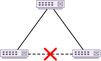
A traditional data centre uses spanning-tree to prevent layer-2 loops. This has been in use for years but does have limitations. To prevent loops, spanning-tree blocks some links and keeps others active, as shown below. The blocked links are ready to use in case the active links fail. If a link does fail, spanning-tree runs the SPF algorithm to decide which link to unblock. The link is then transitioned through several states before it is active.
In classic spanning-tree, blocked links are a waste of bandwidth. Modern spanning-tree has improved on this. Link A may be blocking for VLAN A, but it may be active for VLAN B. This is spanning tree’s attempt at load balancing. Unfortunately, this still has problems. For instance, what if there is a lot of traffic on VLAN-A, and VLAN-B is hardly used? In this case, traffic is not load balanced evenly.
Spanning-tree also results in sub-optimal paths. Have a look at the diagram below. If traffic needs to flow between the two bottom switches, it must pass through the top switch first.
One way to improve this situation is EtherChannels. This allows for many active uplinks from a device to a switch, or between two switches. This still has limitations, as the EtherChannel (or LAG) is only between two devices. The failure of a single switch will still cause an outage for the bundle of links.
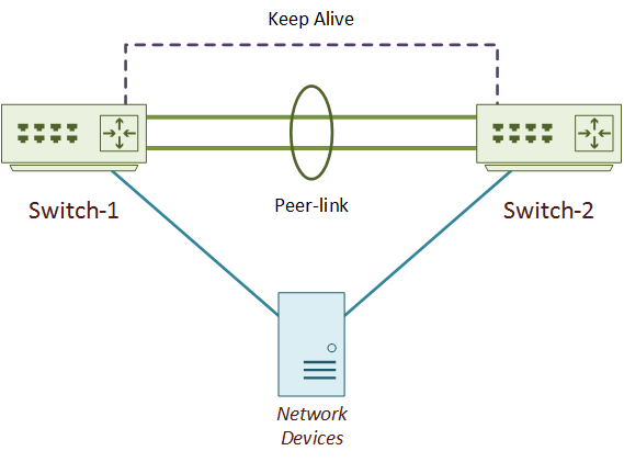
Virtual Port Channels, or vPC’s, are an extension to EtherChannels. They are one method of addressing the limitations of spanning-tree and EtherChannel. As shown below, they do this by enabling a device to create an EtherChannel to two Nexus switches at one time. From the connected device’s perspective, it is still connected to a single switch.
All links in the vPC actively forward traffic. vPC’s are a Multi-Chassis Ethernet Technology (or MCEC), but are not a stack. VSS (Virtual Switching System) on the Catalyst platform is another multi-chassis technology.
Docker: Containers, Networking & Labs
A hands-on course from Network Direction
vPC’s also provide high-availability. As both sets of links are active, vPC’s have a fast convergence time. If a link or a group of links fail, the other links are already forwarding traffic. This is much faster than spanning-tree. It needs to work out a new path, and transition one or more links to the forwarding state.
Any device that supports layer-2 port-channels can connect by a vPC. The device does not need to be vPC aware. Devices include physical servers, firewalls, other switches, and load balancers.
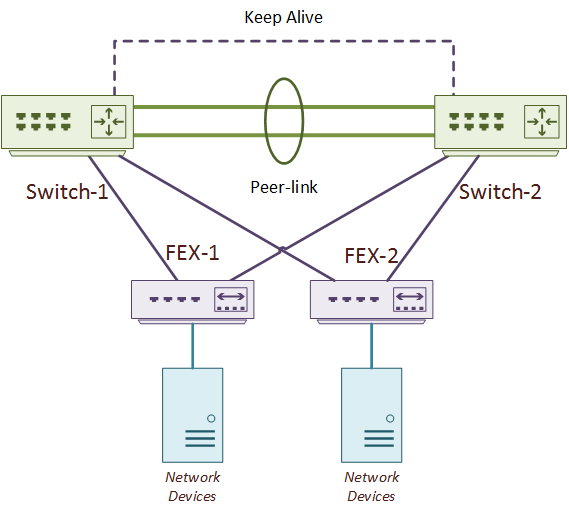
One method of deploying an ASA cluster is by connecting it to a pair of Nexus switches with vPC. As shown below, Fabric Extenders (FEX) can also connect to parent switches with a vPC. In a variation to this topology, the network devices could connect to both FEX’s with vPC.
vPC’s are a Cisco proprietary technology. Other vendors have similar technologies, such as Force 10’s VLT (now Dell). Other technologies which take a different approach include TRILL, FabricPath, and VxLAN.
vPC Deployment
Topology
The vPC topology consists of two Nexus switches, and one or more connected devices. The two switches are peers. The peer switches connect together by two links. These are the peer-link and the keep-alive link. These links make up the backplane of the vPC peer switches. This backplane allows the connected device to see the switch pair as a single device. The connected device can be anything that supports port-channels or LAGs. This includes servers, switches, firewalls, and so on.
There can only be two switches in a vPC topology, which does lead to some scalability issues. Some ways to enhance the data centre network would be to deploy a fabric, with vPC connectivity at the edge. Some fabric examples are Cisco’s FabricPath, or the industry standard VxLAN. Fabrics are beyond the scope of this article.
While vPC eliminates the effects of spanning-tree, spanning-tree itself is not eliminated completely. The network should still use Spanning-Tree. Why? Not all network devices and designs will use vPC. The access layer may use vPC to connect hosts. But the access layer may use traditional connections to the aggregation layer. This needs spanning-tree for loop control.
So what happens if a non-vPC switch connects to a vPC pair? The good news is that vPC peer switches still support spanning-tree. They behave a little different to the traditional model, though. A switch connected by vPC to a Nexus pair will see the pair as a single switch. This means that the pair will appear as a single switch to the rest of the spanning-tree domain. This is possible as both switches synchronise the Bridge ID’s, and the bridge priorities match.
But wait… How can the pair appear to be a single switch to a connected device? Won’t the connected device see spanning-tree BPDU’s coming from both switches?
The short answer: no. Only one switch sends BPDU’s.
vPC has two roles; Primary and Secondary. An election, based on a priority value, decides the roles each switch will assume. Both switches forward traffic in the data plane. But, there are some control plane functions that only the primary switch will handle. One of these is sending BPDU frames. As you look deeper into vPC, you will find other functions that the only the primary switch will handle.
To start using vPC there are two features to enable; vpc and lacp. vPC is an extension to EtherChannels. LACP is still used to exchange control messages with the connected device.
Switch1(config)# feature vpc
Switch1(config)# feature lacp
Keep Alive Link
The keep-alive link sends heartbeats from one peer to another. A peer will use these heartbeats to determine if the other switch is up.
This link is a layer-3 link and is in a separate VRF to keep it isolated from other traffic. This is important, as some failures may lead to either switch thinking that its peer is down, when in fact, it is not. This is a split-brain or dual-active scenario, where both switches think they are primary. The heartbeats over the keepalive link prevent this problem. Both peers can still see each other, even when there’s a failure.
There are two possible ways to deploy this link. The first option is a point-to-point routed connected between the two switches. The second is to use a separate layer-3 network. This may be the distribution, core or management networks.
As this link only carries small heartbeat packets, it does not need a lot of bandwidth. It also does not need a group of links in a port-channel. This means that the keepalive could be a single link between normal ports over a custom VRF. Or, it could be a single point-to-point link between the mgmt0 interfaces.
The following example shows how to configure the keep-alive link using a dedicated port. This is the recommendation for any chassis-based switch with a pair of supervisors.
A dedicated VRF called vpc-keepalive keeps the traffic out-of-band. A dedicated layer-3 (routed) port is added to the VRF and given an IP address.
The next example is another method, which uses the mgmt0 interface as the keepalive link. This is the recommended method for any fixed-switch (not a chassis). This could be a point-to-point link, to run through an OOB management network.
The management port is already routed, and already in its own dedicated VRF.
To verify the keep-alive link, ping the peer-switch from the keep-alive VRF.
Switch1# ping 1.1.1.2 vrf management
PING 1.1.1.2 (1.1.1.2): 56 data bytes
36 bytes from 1.1.1.1: Destination Host Unreachable
Request 0 timed out
64 bytes from 1.1.1.2: icmp_seq=1 ttl=254 time=1.098 ms
64 bytes from 1.1.1.2: icmp_seq=2 ttl=254 time=0.598 ms
64 bytes from 1.1.1.2: icmp_seq=3 ttl=254 time=0.536 ms
64 bytes from 1.1.1.2: icmp_seq=4 ttl=254 time=0.503 ms

--- 1.1.1.2 ping statistics ---
5 packets transmitted, 4 packets received, 20.00% packet loss
round-trip min/avg/max = 0.503/0.683/1.098 ms
vPC Domain
The vPC domain is the logical collection of vPC components. These include the two switches, the links between them, and the vPC member ports. There can only be one domain per switch. Every pair of vPC enabled switches should use a different domain ID.
The domain is where most of the global vPC configuration takes place. This includes assigning the keep-alive link, and the role priority. The switch with the lowest role priority will become the primary.
All configuration relating to the vPC must match on both switches. Configuration is not replicated between the switches by default but is possible.
The example below uses vPC domain ID 10 and uses the keepalive link from earlier.
Verify the domain ID and keepalive link with show vpc brief. In the example below, the vPC is in a failed state, as the peer-link has not yet been configured.
Switch1# show vpc brief
Legend:
                (*) - local vPC is down, forwarding via vPC peer-link

vPC domain id                     : 10
Peer status                       : peer link not configured
vPC keep-alive status             : peer is alive
Configuration consistency status  : failed
Per-vlan consistency status       : failed
Configuration inconsistency reason: vPC peer-link does not exist
Type-2 consistency status         : failed
Type-2 inconsistency reason       : vPC peer-link does not exist
vPC role                          : none established
Number of vPCs configured         : 0
Peer Gateway                      : Disabled
Dual-active excluded VLANs        : -
Graceful Consistency Check        : Disabled (due to peer configuration)
Auto-recovery status              : Disabled
Delay-restore status              : Timer is off.(timeout = 30s)
Delay-restore SVI status          : Timer is off.(timeout = 10s)
Operational Layer3 Peer-router    : Disabled
Peer Link
The peer-link exchanges state information and carries control traffic between peer switches. The peer-link is also known as the Multichassis EtherChannel Trunk. It is this link that forms a virtual Control Plane across the two switches, making them appear as one.
Peer switches use the peer-link for sharing MAC addresses. If one switch adds a MAC to its forwarding table, it sends the MAC to its peer, which adds it to its own forwarding table. This assists in fast convergence if there is a switch failure. For example, if Switch-A fails, Switch-B can continue to forward traffic without disruption. It has already learned all the available MAC addresses.
The peer-link is also responsible for carrying broadcast and multicast traffic. If the network uses multicast, the peer-link needs to be large enough to carry it. Unicast traffic shouldn’t travel across the peer-link unless there is a failure. In this case, the peer switch may need to deliver the traffic.
The peer-link should have at least two 10G interfaces in a port-channel. Depending on the amount of traffic, the link may need to be larger. The peer-link needs to carry all the VLANs that appear on vPC member ports. If it doesn’t, there will be consistency errors on those ports.
During configuration, the keep-alive link should be up and in operation before peer-link configuration.
In the example below, the peer-link is a two-interface port channel. The configuration is the same on both switches.
Switch1(config)# interface eth 1/1-2
Switch1(config-if-range)# channel-group 10 mode active
Switch1(config-if-range)# no shut
Switch1(config-if-range)# interface port-channel 10
Switch1(config-if)# no shut
Switch1(config-if)# switchport
Switch1(config-if)# switchport mode trunk
Switch1(config-if)# vpc peer-link
2017 Jan  4 01:02:03 Switch1 %$ VDC-1 %$ stp: Please note that spanning tree port type is changed to "network" port type on vPC peer-link. This will enable spanning tree Bridge Assurance on vPC peer-link provided the STP Bridge Assurance (which is enabled by default) is not disabled.
The Peer status now shows that the peer adjacency formed ok.
Switch1# sh vpc brief
Legend:
                (*) - local vPC is down, forwarding via vPC peer-link

vPC domain id                     : 10
Peer status                       : peer adjacency formed ok
vPC keep-alive status             : peer is alive
Configuration consistency status  : success
Per-vlan consistency status       : success
Type-2 consistency status         : success
vPC role                          : primary
Number of vPCs configured         : 0
Peer Gateway                      : Disabled
Dual-active excluded VLANs        : -
Graceful Consistency Check        : Enabled
Auto-recovery status              : Disabled
Delay-restore status              : Timer is off.(timeout = 30s)
Delay-restore SVI status          : Timer is off.(timeout = 10s)
Operational Layer3 Peer-router    : Disabled

vPC Peer-link status
---------------------------------------------------------------------
id    Port   Status Active vlans
--    ----   ------ -------------------------------------------------
1     Po10   up     1
Ports
Member Ports
Member ports are vPC ports that hosts or other devices connect to. The connected device has to configure its own port-channel for this to be effective.
The configuration is the same on both switches. Different ports numbers are allowed, as long as they match in speed, duplex and so on. The vPC number does not have to match the portchannel number, but it is easier for the administrator if they do.
! Add interfaces into a regular port-channel
Switch1(config)# interface eth 1/20
Switch1(config-if)# channel-group 15 mode active

! Configure the port-channel as a vPC
Switch1(config-if)# interface port-channel 15
Switch1(config-if)# switchport
Switch1(config-if)# vpc 15
The output below shows the new member port. It is currently marked as down, as nothing has been connected yet.
Switch1# show vpc brief
Legend:
                (*) - local vPC is down, forwarding via vPC peer-link

vPC domain id                     : 10
Peer status                       : peer adjacency formed ok
vPC keep-alive status             : peer is alive
Configuration consistency status  : success
Per-vlan consistency status       : success
Type-2 consistency status         : success
vPC role                          : primary
Number of vPCs configured         : 1
Peer Gateway                      : Disabled
Dual-active excluded VLANs        : -
Graceful Consistency Check        : Enabled
Auto-recovery status              : Disabled
Delay-restore status              : Timer is off.(timeout = 30s)
Delay-restore SVI status          : Timer is off.(timeout = 10s)
Operational Layer3 Peer-router    : Disabled

vPC Peer-link status
---------------------------------------------------------------------
id    Port   Status Active vlans
--    ----   ------ -------------------------------------------------
1     Po10   up     1

vPC status
----------------------------------------------------------------------------
Id    Port          Status Consistency Reason                Active vlans
--    ------------  ------ ----------- ------                ---------------
20    Po15          down*  success     success               -
Orphan Ports
An orphan port is a non-vPC port that is on a vPC enabled switch. This is any device that connects to only one of the switches, not both. An example of this is a server’s management port.
An orphan port may carry any VLAN, even if it is present on a vPC member port or on the peer-link.
Switch1# show vpc orphan-ports
Note:
--------::Going through port database. Please be patient.::--------

VLAN           Orphan Ports
-------        -------------------------
1              Eth1/11
Compatibility Conditions
There are several conditions which must match on all ports in the vPC:
- Port modes
- Port speeds (whether manual or negotiated)
- MTU
- Duplex
- Ethernet layer (switchport or no switchport)
- Storm control
- Flow control
- Native VLAN
- Allowed VLAN list
Additionally, SPAN and ERSPAN ports are not allowed in a vPC.
Peer switches use the peer-link to check for compatibility and misconfigurations. Type-1 misconfigurations are quite serious. They result in the suspension of the port channel on one or both peers. Type-2 misconfigurations are at little more forgiving. If there is a Type-2 error, the administrator will receive a syslog message.
If there is a VLAN mismatch, only the mismatched VLAN will be suspended.
See the global consistency parameters with the show vpc consistency-parameters global command.
Switch1# show vpc consistency-parameters global

    Legend:
        Type 1 : vPC will be suspended in case of mismatch

Name                        Type  Local Value            Peer Value
-------------               ----  ---------------------- -----------------------
QoS (Cos)                   2     ([0-7], [], [], [],    ([0-7], [], [], [],
                                  [], [])                [], [])
Network QoS (MTU)           2     (1500, 1500, 1500,     (1500, 1500, 1500,
                                  1500, 1500, 1500)      1500, 1500, 1500)
Network Qos (Pause:         2     (F, F, F, F, F, F)     (F, F, F, F, F, F)
T->Enabled, F->Disabled)
Input Queuing (Bandwidth)   2     (0, 0, 0, 0, 0, 0)     (0, 0, 0, 0, 0, 0)
Input Queuing (Absolute     2     (F, F, F, F, F, F)     (F, F, F, F, F, F)
Priority: T->Enabled,
F->Disabled)
Output Queuing (Bandwidth   2     (0, 0, 0, 0, 0, 0)     (0, 0, 0, 0, 0, 0)
Remaining)
Output Queuing (Absolute    2     (T, F, F, F, F, F)     (T, F, F, F, F, F)
Priority: T->Enabled,
F->Disabled)
Vlan to Vn-segment Map      1     No Relevant Maps       No Relevant Maps
STP Mode                    1     Rapid-PVST             Rapid-PVST
STP Disabled                1     None                   None
STP MST Region Name         1     ""                     ""
STP MST Region Revision     1     0                      0
STP MST Region Instance to  1
 VLAN Mapping
STP Loopguard               1     Disabled               Disabled
STP Bridge Assurance        1     Enabled                Enabled
STP Port Type, Edge         1     Normal, Disabled,      Normal, Disabled,
BPDUFilter, Edge BPDUGuard        Disabled               Disabled
STP MST Simulate PVST       1     Enabled                Enabled
Nve Admin State, Src Admin  1     None                   None
 State, Secondary IP, Host
 Reach Mode
Nve Vni Configuration       1     None                   None
Allowed VLANs               -     1                      1
Local suspended VLANs       -     -                      -
See consistency problems on a specific interface with the show vpc consistency-parameters interface interface command.
Switch1# show vpc consistency-parameters interface port-channel 15

    Legend:
        Type 1 : vPC will be suspended in case of mismatch

Name                        Type  Local Value            Peer Value
-------------               ----  ---------------------- -----------------------
STP Port Type               1     Default                Default
STP Port Guard              1     Default                Default
STP MST Simulate PVST       1     Default                Default
vPC card type               1     N9K TOR                N9K TOR
Allowed VLANs               -     1                      1
Local suspended VLANs       -     -                      -
Migrated Comment:
Excellent Videos
Rajinder (unverified) 2018-04-29 22:16
Very Well explained and beautifully animated. Please keep your good work.
Migrated Comment:
Thanks!
Luke Robertson 2018-04-30 09:11
Thanks Rajinder, I appreciate your comments cool
Thanks.
I was surprised to see that this site has been going unnoticed, despite the brilliant video explanation.
Thanks for the compliment. I don’t put a lot of effort into advertising the site, which is guess is why it’s not very well known.
There seems to be a problem in the middle of the page.
Please search for the following content in your web browser
“More information in the Etherchannel series”
and “[rtbs name=”keepalive-link”]