
ASA Cluster Configuration
Welcome to ASA cluster configuration! It’s possible that you are here because you have already read the ASA Clustering article. If so, that’s great! If not, please consider having a look there first. It contains a lot of background information on how clustering works. If you’re already pretty good on the theory, then read on…
Prerequisites
Before beginning, you will need a suitable ASA and IOS version. Clustering is not supported on the 5506-X or the ASAv. If you using something other than the 5585 series, you will need at least 9.1(4). This article assumes you’re using 9.6.
Cable the switches and ASA’s before beginning configuration. This example assumes the use of a Nexus switch pair with vPC already cabled and configured. The ASA should have the management, CCL, and data interfaces cabled to the switches.
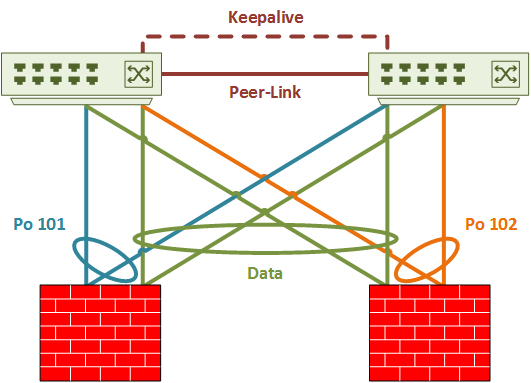
As shown in the logical diagram below, Port-channel’s 101 and 102 are the CCL’s. Both CCL’s use VLAN 100. Data interfaces are in spanned-etherchannel mode. They will use sub-interfaces, which requires trunking.
While not shown explicitly, this cluster uses eight ports per ASA. Four will be for the data interfaces, and four will be for the CCL.
Nexus Switch Config
Start by configuring the Nexus switches. The vPC base configuration is not shown here, but you can find it in the Nexus vPC article.
Make sure a suitable load-balancing method is set. The best options are src-dst-ip or src-dst-ip-l4port.
Hashing Method
Switch-1# show port-channel load-balance
 System config:
  Non-IP: src-dst mac
  IP: src-dst ip-l4port  rotate 0
Port Channel Load-Balancing Configuration for all modules:
Module 1:
  Non-IP: src-dst mac
  IP: src-dst ip-l4port rotate 0
Next, configure the CCL ports. On the switch pair, there is a port-channel for each ASA CCL. The CCL uses four ports per ASA, spread across the switch pair. ASA-1 uses vPC 101 and ASA-2 uses vPC 102.
The CCL link adds 100 bytes of overhead, so the MTU size has to be at least 1600 bytes. The example below uses an MTU of 9126.
! CCL VLAN
Switch-1(config)# vlan 100
Switch-1(config-vlan)# name CCL_Link

! ASA-1 CCL
Switch-1(config)# interface ethernet 110/1/31-32
Switch-1(config-if-range)# description ASA-1 CCL
Switch-1(config-if-range)# channel-group 101 mode active

Switch-1(config)# interface po 101
Switch-1(config-if)# description ASA-1 CCL
Switch-1(config-if)# switchport
Switch-1(config-if)# switchport mode access
Switch-1(config-if)# switchport access vlan 100
Switch-1(config-if)# mtu 9216
Switch-1(config-if)# vpc 101

! ASA-2 CCL
Switch-1(config)# interface ethernet 110/1/33-34
Switch-1(config-if-range)# description ASA-2 CCL
Switch-1(config-if-range)# channel-group 102 mode active

Switch-1(config)# interface port-channel 102
Switch-1(config-if)# description ASA-2 CCL
Switch-1(config-if)# switchport
Switch-1(config-if)# switchport mode access
Switch-1(config-if)# switchport access vlan 100
Switch-1(config-if)# mtu 9216
Switch-1(config-if)# vpc 102
There are four data interfaces per ASA. All the data interfaces from the entire cluster are in a single vPC. This is because of spanned-etherchannel. The Nexus switches see the ASA cluster as a whole, rather than as two separate units. vPC 100 is used for the data interfaces.
By default, the Nexus port-channel hashing mode is adaptive. When a link enters or leaves an etherchannel, the switch regenerates all the hashes. The hashes are redistributed across the links. This is not ideal for an ASA cluster, as it causes connections to land on different cluster members. For this reason, the hash-distribution is set to fixed on the port-channel.
! Data Interfaces
Switch-1(config)# interface ethernet 110/1/27-28
Switch-1(config-if-range)# description ASA-1 Data
Switch-1(config-if-range)# channel-group 100 mode active

Switch-1(config)# interface ethernet 110/1/29-30
Switch-1(config-if-range)# desc ASA-2 Data
Switch-1(config-if-range)# channel-group 100 mode active

Switch-1(config)# interface port-channel 100
Switch-1(config-if)# shutdown
Switch-1(config-if)# description ASA-Cluster
Switch-1(config-if)# switchport
Switch-1(config-if)# switchport mode trunk
Switch-1(config-if)# no lacp graceful-convergence
Switch-1(config-if)# port-channel port hash-distribution fixed
This interface level command does not take effect until the next member link event(link down/up/no shutdown/shutdown). Do you still want to continue(y/n)? [yes] y
Switch-1(config-if)# mtu 9216
Switch-1(config-if)# vpc 100
Switch-1(config-if)# no shut
ASA Configuration
ASA Configuration takes place in three main phases:
- Preparation
- Bootstrap Config
- Additional parameters
Preparation
Enable jumbo frames to support the cluster control link. This is a global configuration command.
ASA-1(config)# jumbo-frame reservation
WARNING: This command will take effect after the running-config is saved and the system has been rebooted. Command accepted.

INFO: Interface MTU should be increased to avoid fragmenting
      jumbo frames during transmit
This example uses spanned-etherchannel mode. While setting the interface mode, check if there are any problems with the exiting config.
! Check for problems, and enable spanned-etherchannel mode
ASA-1(config)# cluster interface-mode spanned check-details
Cluster interface-mode has been changed to 'spanned' mode successfully. Please complete interface and routing configuration before enabling clustering.

! Alternatively, enable spanned etherchannel mode without the checks
ASA-2(config)# cluster interface-mode spanned
Cluster interface-mode has been changed to 'spanned' mode successfully. Please complete interface and routing configuration before enabling clustering.
Use a vss-id on a data interface when it connects to a switch by VSS or vPC. A VSS ID, 1 or 2, represents the switch that the port connects to. When using multi-context mode, configuration takes place in the system context.
The span-cluster keyword indicates that this interface is in spanned-etherchannel mode. vss-load-balance indicates that this interface connects to a VSS or vPC enabled switch.
Do not change the load balance hashing method. This may result in flow asymmetry.
! Ports connecting to Switch-1
ASA-1(config)# int gi 0/4
ASA-1(config-if)# description Data
ASA-1(config-if)# channel-group 10 mode active vss-id 1
INFO: security-level, delay and IP address are cleared on GigabitEthernet0/0.
ASA-1(config-if)# no shut

ASA-1(config-if)# int gi 0/6
ASA-1(config-if)# description Data
ASA-1(config-if)# channel-group 10 mode active vss-id 1
INFO: security-level, delay and IP address are cleared on GigabitEthernet0/2.
ASA-1(config-if)# no shut

! Ports connecting to Switch-2
ASA-1(config-if)# interface gigabitEthernet 0/5
ASA-1(config-if)# description Data
ASA-1(config-if)# channel-group 10 mode active vss-id 2
INFO: security-level, delay and IP address are cleared on GigabitEthernet0/1.
ASA-1(config-if)# no shut

ASA-1(config-if)# interface gigabitEthernet 0/7
ASA-1(config-if)# description Data
ASA-1(config-if)# channel-group 10 mode active vss-id 2
INFO: security-level, delay and IP address are cleared on GigabitEthernet0/3.
ASA-1(config-if)# no shut

! Configure the Port Channel
ASA-1(config)# interface port-channel 10
ASA-1(config-if)# description Data Interface
ASA-1(config-if)# port-channel span-cluster vss-load-balance
INFO: lacp port-priority on member interfaces of channel-group Port-channel10 will be controlled by CLACP.
INFO: CLACP vss-load-balance is enabled. This assumes all cluster units have the same interfaces connected to two switches in the VSS or VPC pair and each unit has the same number of interfaces connected to both switches (vss-id 1 and 2).
Interfaces still need normal configuration. This includes a security level, name, and IP. This example first creates sub-interfaces.
You may be using multiple context mode. If so, create sub-interfaces and assign VLANs in the system context. The rest of the configuration happens inside the context.
Each interface needs to have a vMAC configured. This becomes important when removing a member from the cluster. When using multi-context mode, auto-generation may be useful.
ASA-1(config)# interface port-channel 10.301
ASA-1(config-subif)# vlan 301
ASA-1(config-subif)# nameif inside
INFO: Security level for "inside" set to 100 by default.
ASA-1(config-subif)# ip address 192.168.0.254 255.255.255.0
ASA-1(config-subif)# mac-address 000c.f142.1111

ASA-1(config)# interface port-channel 10.302
ASA-1(config-subif)# vlan 302
ASA-1(config-subif)# nameif DMZ
INFO: Security level for "DMZ" set to 0 by default.
ASA-1(config-subif)# security-level 50
ASA-1(config-subif)# ip address 172.16.0.254 255.255.255.0
ASA-1(config-subif)# mac-address 000c.f142.2222

ASA-1(config)# interface port-channel 10.303
ASA-1(config-subif)# vlan 303
ASA-1(config-subif)# nameif Outside
INFO: Security level for "Outside" set to 0 by default.
ASA-1(config-subif)# ip address 10.0.0.254 255.255.255.0
ASA-1(config-subif)# mac-address 000c.f142.3333
Bootstrap Config
Each ASA needs a few settings before joining the cluster. This is the Bootstrap Config. Once the Bootstrap config is complete, configuration happens on the primary member.
The bootstrap config should be completed over a console connection.
If using contexts, complete the config in the system execution space.
Management Interfaces
The first step is to create a pool of IP’s for the management interface. Two ASA’s means that there needs to be two IP’s in the pool. The pool is assigned when configuring the management interface.
The management interface uses another IP, as well as the pool. This is theIP of the cluster, and is set the same on each member.
ASA-1(config)# ip local pool mgmt 10.10.10.104-10.10.10.105 mask 255.255.255.0

ASA-1(config)# interface management 0/0
ASA-1(config-if)# nameif management
INFO: Security level for "management" set to 0 by default.
ASA-1(config-if)# ip address 10.10.10.103 255.255.255.0 cluster-pool mgmt
ASA-1(config-if)# security-level 100
ASA-1(config-if)# no shut
Cluster Control Link
The Cluster Control Link is a port channel. This is a unique port-channel on each ASA, connecting to Nexus switches by vPC. The port-channel is not given a name, and cannot be a management interface.
The documentation says to configure the port-channel with mode on. The Cisco Live BRKSEC-3032 on the other hand, recommends using mode active.
ASA-1(config)# int gigabitEthernet 0/0
ASA-1(config-if)# description CCL
ASA-1(config-if)# channel-group 1 mode active
INFO: security-level, delay, IP address, cts manual and bfd configuration are cleared on GigabitEthernet0/0.
ASA-1(config-if)# no shut

ASA-1(config-if)# int gigabitEthernet 0/1
ASA-1(config-if)# description CCL
ASA-1(config-if)# channel-group 1 mode active
INFO: security-level, delay, IP address, cts manual and bfd configuration are cleared on GigabitEthernet0/1.
ASA-1(config-if)# no shut

ASA-1(config-if)# int gigabitEthernet 0/2
ASA-1(config-if)# description CCL
ASA-1(config-if)# channel-group 1 mode active
INFO: security-level, delay, IP address, cts manual and bfd configuration are cleared on GigabitEthernet0/2.
ASA-1(config-if)# no shut

ASA-1(config-if)# int gigabitEthernet 0/3
ASA-1(config-if)# description CCL
ASA-1(config-if)# channel-group 1 mode active
INFO: security-level, delay, IP address, cts manual and bfd configuration are cleared on GigabitEthernet0/3.
ASA-1(config-if)# no shut

ASA-1(config)# interface port-channel 1
ASA-1(config-if)# description CCL
ASA-1(config-if)# no shut
Cluster Configuration
The configuration below shows a cluster group with the name TwoNodeCluster. Each node has a local-unit name. This is useful when looking though syslogs, and sending commands to a specific member.
The cluster-interface command selects the Cluster Control Link, and sets an IP address.
As ASA-1 has the better priority, it should win any election and become primary. Really though, the first ASA in the cluster will become the primary. It will continue to hold the role until a failure, or a new primary is manually selected.
Enable the cluster. The ASA warns of incompatible configuration, and removes it. Don’t forget to set the MTU
After a while, the ASA will transition into the MASTER (primary) role. When adding more ASA’s, the configuration is replicated from the master.
Additional Parameters
There are a few more parameters to consider. The first is console replication. This tells the secondaries to send any console messages to the primary ASA.
The health-check holdtime is the ‘heartbeat’ interval, which is three seconds by default. Adding vss-enabled tells the ASA that it’s connected to two switches, not one. This prevents the cluster from thinking links are down if one of the Nexus switches reboots.
There’s also a feature called conection rebalancing. If a member gets overloaded, it can hand some of it’s connections to other members. This sounds good, but isn’t recommended. There are two problems. One is that it takes effort from an already overloaded member to do this. The other, is that it introduces traffic asymmetry.
ASA-1(config)# cluster group TwoNodeCluster
ASA-1(cfg-cluster)# console-replicate
ASA-1(cfg-cluster)# health-check holdtime 3 vss-enabled
ASA-1(cfg-cluster)# conn-rebalance frequency 5

! This is only on the master unit
Cluster Management
Now that the cluster is up and running, it’s time to verify it. Below are a few reference commands to use.
Check the interface mode:
ASA-1# show cluster interface-mode
cluster interface-mode spanned
List the units in the cluster:
ASA-1# show cluster info
Cluster TwoNodeCluster: On
    Interface mode: spanned
    This is "ASA-1" in state MASTER
        ID        : 0
        Version   : 9.6(2)
        Serial No.: FCH20507HSY
        CCL IP    : 192.168.254.1
        CCL MAC   : 2c33.1151.2d47
        Last join : 15:51:26 UTC Jan 19 2017
        Last leave: N/A
Other members in the cluster:
    Unit "ASA-2" in state SLAVE
        ID        : 1
        Version   : 9.6(2)
        Serial No.: FCH20507HYC
        CCL IP    : 192.168.254.2
        CCL MAC   : 2c33.1151.3103
        Last join : 15:53:09 UTC Jan 19 2017
        Last leave: N/A
Show the health status of the cluster:
ASA-1# show cluster info health
Member ID to name mapping:
  0 - ASA-1(myself)   1 - ASA-2

                         0        1
Port-channel10           up       up
Management0/0            up       up
Port-channel1            up       up

ips (policy off)         None     None
sfr (policy off)         up       up
Unit overall             healthy   healthy
Cluster overall          healthy
Remove the local unit from the cluster. This does not remove the cluster config:
ASA-1(config)# cluster group TwoNodeCluster
ASA-1(cfg-cluster)# no enable
Cluster disable is performing cleanup..done.
All data interfaces have been shutdown due to clustering being disabled. To recover either enable clustering or remove cluster group configuration.

Cluster unit ASA-1 transitioned from MASTER to DISABLED
Remove a remote unit from the cluster. This also does not remove the cluster configuration:
ASA-1(config)# cluster remove unit ASA-2
WARNING: Clustering will be disabled on unit ASA-2. To bring it back
to the cluster please logon to that unit and re-enable clustering
ASA-1(config)#
WARNING: dynamic routing is not supported on management interface when cluster interface-mode is 'spanned'.  If dynamic routing is configured on any management interface, please remove it.

Cluster unit ASA-1 transitioned from SLAVE to MASTER
Manually select a MASTER (primary) member.
ASA-1(config)# cluster master unit ASA-2
INFO:Cluster unit ASA-1 transitioned from MASTER to SLAVEWait for existing master to quit. Use "show cluster info"to check status. Use "cluster remove unit " to forcemaster unit out of the cluster if for some reason it refusesto quit within reasonable time
Run a command on all members:
ASA-1# cluster exec show version | include Version
ASA-2(LOCAL):*********************************************************
Cisco Adaptive Security Appliance Software Version 9.6(2)
Device Manager Version 7.6(2)150
Baseboard Management Controller (revision 0x1) Firmware Version: 2.4

ASA-1:****************************************************************
Cisco Adaptive Security Appliance Software Version 9.6(2)
Device Manager Version 7.6(2)150
Baseboard Management Controller (revision 0x1) Firmware Version: 2.4