

Site to Site VPN’s in FMC
Last Updated: [last-modified] (UTC)
Firewalls running Threat Defence support site to site (AKA LAN-to-LAN) VPNs. They’re slightly different though, as the VPN is configured in FMC, not on the device itself.
In this article, we’ll look at how to configure a site-to-site VPN through FMC.
Please note, this applies to FMC managing devices that run FTD. Regular ASA with Firepower Services do not have their VPN’s configured in FMC.
It is recommended to have an understanding of IPSec, especially phase-1 and phase-2, before starting
[maxbutton id=”4″ text=”IPSec Basics” url=”https://networkdirection.net/IPSec+Basics”][maxbutton id=”4″ text=”ASA VPN” url=”https://networkdirection.net/ASA+Policy+Based+VPN”]
Topologies
The first thing to be aware of is the topologies that are supported. There are three topology types to choose from:
- Point to Point – This is a simple topology between two endpoints. In FMC, A and B nodes need to be defined
- Hub and Spoke – A group of spoke sites creating tunnels to a hub site
- Full Mesh – A group of multipoint tunnels, where any device can connect to any other
Each device in any of these topologies is called an endpoint. At least one endpoint will be a device managed in FMC.
Any device in your VPN topology that’s not FMC managed is called an Extranet device. This includes devices in your network that don’t run threat defence, devices outside of your network (such as a router in a partner network), and Threat Defence devices managed by a different FMC server.
We can use FMC to push VPN config to remove FTD devices. This is possible for devices managed in our FMC, or devices managed with another FMC server (such as a remote office managed by a different team).
Each endpoint has a protected network associated with it. This is, as the name suggests, the network that’s behind the VPN device. The ultimate goal of the VPN is for the protected networks to communicate with each other.
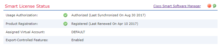
No special licensing is required for the VPN, as long as export-controlled features is enabled.

Configuration
IKE Policies and IPSec Proposals
Each endpoint can be authenticated using either certificates or preshared keys. Preshared keys may be automatic if FMC manages all the endpoints.
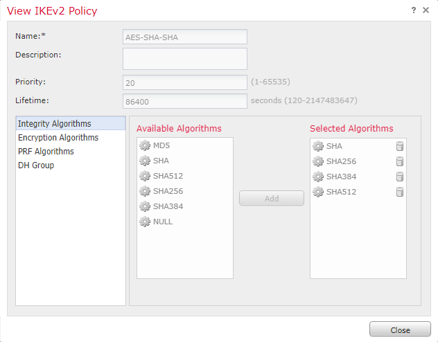
There are some predefined IKE policies that you can use, or you can create your own:
- Go to the Objects tab
- Browse to VPN, then either IKEv1 or IKEv2
As shown below, you can select the algorithms that you want to use. The same applies to IPSec proposals.

Recommended Firepower Reading
Cisco Firepower 6.x with Firepower Threat Defense (FTD): Next Generation Firewall (NGFW)

Topology
We’ll now create a point-to-point VPN that connects to a third-party device.
- Browse to Devices -> VPN -> Site To Site
- Click Add VPN -> Firepower Threat Defence Device
- Enter a name for the topology
- Select a topology type (point to point in our case)
- Select the version of IKE to use (IKEv2 is recommended)
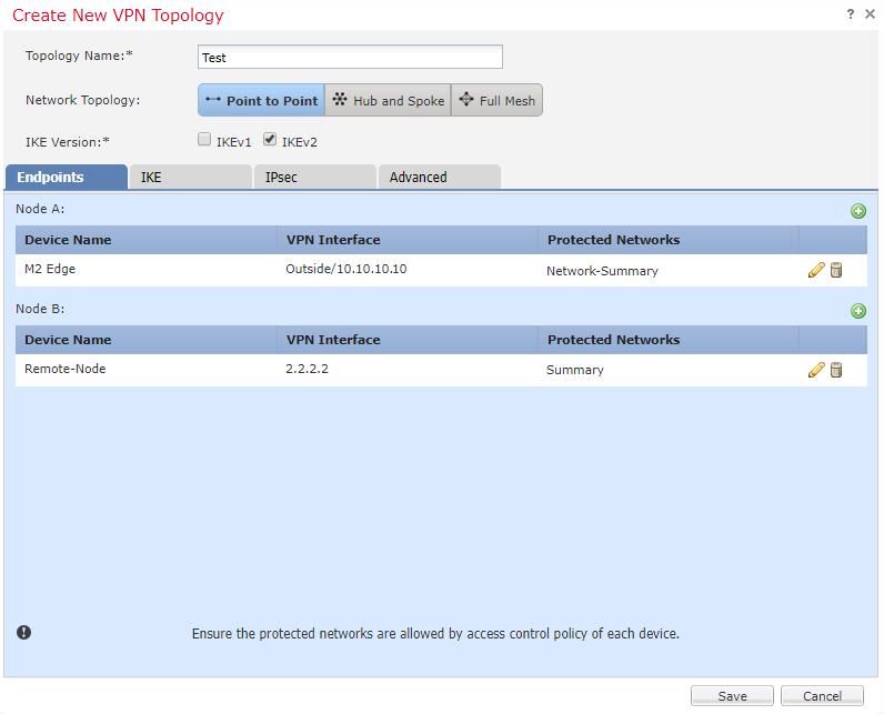

Now we need to define our first endpoint (Node A).
- Make sure you’re on the Endpoints tab
- Next to Node A, click the green Add button
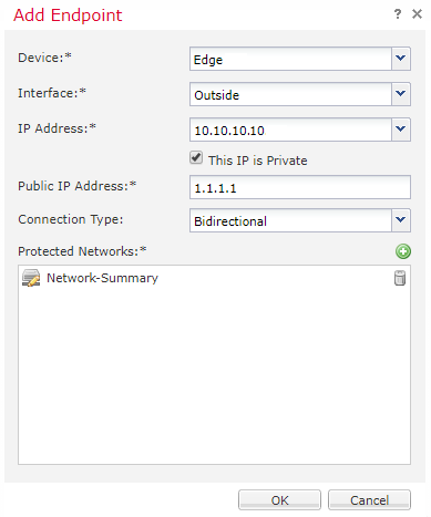
- Select a Threat Defence device that your FMC manages from the list
- Select an interface that the VPN will be established on
- If there is more than one IP address on this interface, select the one to use
- If this is a private IP address (non-routable over the internet), tick the This IP is Private checkbox, and enter the corresponding public IP
- Select the Connection Type
- Bidirectional – Either node can negotiate the VPN
- Answer-Only – The local node will respond when the remote node negotiates the VPN
- Originate-Only – The local node will negotiate the VPN, but will not respond if the remote tries to negotiate
- Click the green Add button next to Protected Networks
- Add one or more networks behind this device, that will be accessible over the VPN
- From FMC 6.2.3, you have the option of using a subnet/IP address object, or an extended access list

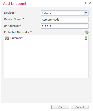
Now, configure the remote endpoint (not managed by us):
- Next to Node B, click the green Add button
- Select Extranet as the device
- Enter a friendly Device Name
- Enter the IP address of the device
- For version 6.2.3 and newer, there will be an option to add a certificate map (we don’t need it, as we’re using preshared keys)
- As before, add a protected network

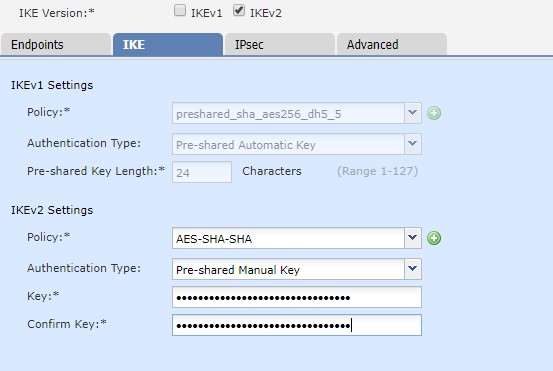
Next, we configure IKE (the phase-1 tunnel). The settings available to us are determined by the version of IKE that we’re using.
- Go to the IKE tab
- Select a suitable policy (we’re using the predefined AES-SHA-SHA policy)
- Select the authentication type
- A preshared manual key is entered at both ends manually
- A preshared automatic key is managed by FMC. This requires FMC to manage both ends
- A certificate can be used, but it requires a trustpoint to be configured

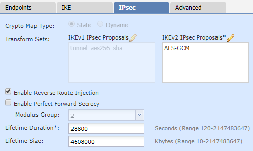
And now we configure IPSec (phase-2 tunnel):
- Go to the IPSec tab
- Select a suitable IPSec proposal (If you’re not sure, leave the defaults in place)
- Enable Reverse Route Injection to add protected networks into the local routing table
- Optionally, enable Perfect Forward Secrecy. If you’re not sure, leave it enabled

Additional Configuration
There are a few final things that you may want to consider for your environment.
NAT Exemption – If you use NAT, you will need to create an exemption for the traffic going over the VPN.
Dynamic Routing – Reverse Route Injection gets the route into the local routing table, but it doesn’t go any further. If you want to advertise this route, you need to redistribute it into your IGP.
Policy Deployment – Remember that your changes will not take effect until you deploy them to your devices.
Verification and Monitoring
The simplest place to check the status of your VPN is in FMC.
Browse to System -> Health -> Events. Then click on VPN Status.
The remaining verification takes place on the FTD CLI. When you are at the CLI, run system support diagnostic-cli to get the Classic-ASA style console.
From here, run packet-tracer to simulate traffic between the protected networks.
NOTE: I’ve used some fake IP’s here, so I don’t share any real network information.
firepower# packet-tracer in inside icmp 10.6.26.201 8 0 10.8.1.1

Phase: 1
Type: UN-NAT
Subtype: static
Result: ALLOW
Config:
nat (Inside,Outside) source static Network-Test Network-Test destination static Network-Remote Network-Remote description VPN Exemption
Additional Information:
NAT divert to egress interface Outside
Untranslate 10.8.1.1/0 to 10.8.1.1/0

Phase: 2
Type: ACCESS-LIST
Subtype: log
Result: ALLOW
Config:
access-group CSM_FW_ACL_ global
access-list CSM_FW_ACL_ advanced trust icmp any any rule-id 268436517 event-log flow-end
access-list CSM_FW_ACL_ remark rule-id 268436517: PREFILTER POLICY: Site Prefilter
access-list CSM_FW_ACL_ remark rule-id 268436517: RULE: ICMP
Additional Information:

Phase: 3
Type: CONN-SETTINGS
Subtype:
Result: ALLOW
Config:
class-map class-default
 match any
policy-map global_policy
 class class-default
  set connection advanced-options UM_STATIC_TCP_MAP
  set connection decrement-ttl
service-policy global_policy global
Additional Information:

Phase: 4
Type: NAT
Subtype:
Result: ALLOW
Config:
nat (Inside,Outside) source static Network-Test Network-Test destination static Network-Remote Network-Remote description VPN Exemption
Additional Information:
Static translate 10.6.26.201/0 to 10.6.26.201/0

Phase: 5
Type: NAT
Subtype: per-session
Result: ALLOW
Config:
Additional Information:

Phase: 6
Type: IP-OPTIONS
Subtype:
Result: ALLOW
Config:
Additional Information:

Phase: 7
Type: INSPECT
Subtype: np-inspect
Result: ALLOW
Config:
Additional Information:

Phase: 8
Type: VPN
Subtype: encrypt
Result: ALLOW
Config:
Additional Information:

Phase: 9
Type: NAT
Subtype: rpf-check
Result: ALLOW
Config:
nat (Inside,Outside) source static Network-Test Network-Test destination static Network-Remote Network-Remote description VPN Exemption
Additional Information:

Phase: 10
Type: FLOW-CREATION
Subtype:
Result: ALLOW
Config:
Additional Information:
New flow created with id 41815442, packet dispatched to next module

Phase: 11
Type: ROUTE-LOOKUP
Subtype: Resolve Egress Interface
Result: ALLOW
Config:
Additional Information:
found next-hop 10.222.254.22 using egress ifc  Outside

Phase: 12
Type: FLOW-LOOKUP
Subtype:
Result: ALLOW
Config:
Additional Information:
Found flow with id 41634632, using existing flow

Phase: 13
Type: CAPTURE
Subtype:
Result: ALLOW
Config:
Additional Information:
MAC Access list

Result:
input-interface: Outside
input-status: up
input-line-status: up
output-interface: Outside
output-status: up
output-line-status: up
Action: allow
Now, let’s confirm phase-1 (IKE). You may find that the commands below do not return any data initially.
This is because FTD will not attempt to bring the tunnel up until it sees some traffic trying to pass over it. A ping or packet-trace can help with this. Configuring IP SLA somewhere else in the network may be useful to keep the tunnel up.
! IKEv1 or v2 can be used

firepower# show crypto ikev1 sa

IKEv1 SAs:

   Active SA: 1
    Rekey SA: 0 (A tunnel will report 1 Active and 1 Rekey SA during rekey)
Total IKE SA: 1

1   IKE Peer: 258.6.18.25
    Type    : L2L             Role    : initiator
    Rekey   : no              State   : MM_ACTIVE
Now, have a look at phase-2 (IPSec). In particular, look for encaps and decaps.
Encaps are packets that we encapsulate and send over the VPN. Decaps are packets that are sent over the VPN to us, that we need to decapsulate.
firepower# sh crypto ip sa
interface: Outside
    Crypto map tag: CSM_Outside_map, seq num: 2, local addr: 10.222.254.2

      access-list CSM_IPSEC_ACL_1 extended permit ip 10.6.26.0 255.255.255.0 10.8.0.0 255.255.0.0
      local ident (addr/mask/prot/port): (10.6.26.0/255.255.255.0/0/0)
      remote ident (addr/mask/prot/port): (10.8.0.0/255.255.0.0/0/0)
      current_peer: 258.6.18.25


      #pkts encaps: 43, #pkts encrypt: 43, #pkts digest: 43     ! We are encapsulating traffic and sending
      #pkts decaps: 0, #pkts decrypt: 0, #pkts verify: 0        ! We are not getting return traffic to decapsulate
      #pkts compressed: 0, #pkts decompressed: 0
      #pkts not compressed: 43, #pkts comp failed: 0, #pkts decomp failed: 0
      #pre-frag successes: 0, #pre-frag failures: 0, #fragments created: 0
      #PMTUs sent: 0, #PMTUs rcvd: 0, #decapsulated frgs needing reassembly: 0
      #TFC rcvd: 0, #TFC sent: 0
      #Valid ICMP Errors rcvd: 0, #Invalid ICMP Errors rcvd: 0
      #send errors: 0, #recv errors: 0

      local crypto endpt.: 10.222.254.2/4500, remote crypto endpt.: 258.6.18.25/4500
      path mtu 1500, ipsec overhead 82(52), media mtu 1500
      PMTU time remaining (sec): 0, DF policy: copy-df
      ICMP error validation: disabled, TFC packets: disabled
      current outbound spi: 6EAB4C07
      current inbound spi : B53ECF25

    inbound esp sas:
      spi: 0xB53ECF25 (3040792357)
         transform: esp-aes-256 esp-sha-hmac no compression
         in use settings ={L2L, Tunnel,  NAT-T-Encaps, PFS Group 2, IKEv1, }
         slot: 0, conn_id: 12288, crypto-map: CSM_Outside_map
         sa timing: remaining key lifetime (kB/sec): (3915000/26892)
         IV size: 16 bytes
         replay detection support: Y
         Anti replay bitmap:
          0x00000000 0x00000001
    outbound esp sas:
      spi: 0x6EAB4C07 (1856719879)
         transform: esp-aes-256 esp-sha-hmac no compression
         in use settings ={L2L, Tunnel,  NAT-T-Encaps, PFS Group 2, IKEv1, }
         slot: 0, conn_id: 12288, crypto-map: CSM_Outside_map
         sa timing: remaining key lifetime (kB/sec): (3914997/26892)
         IV size: 16 bytes
         replay detection support: Y
         Anti replay bitmap:
          0x00000000 0x00000001
If you’re using Reverse Route Injection, then you should check that the route is in the routing table.
Start by checking if the route is in FTD, as shown below. Then check that it’s being redistributed into your IGP successfully.
firepower# show route static
! ---Output removed for brevity---

Gateway of last resort is 10.225.254.54 to network 0.0.0.0

S*       0.0.0.0 0.0.0.0 [1/0] via 10.222.254.2, Outside
V        10.8.0.0 255.255.0.0 connected by VPN (advertised), Outside
References
Cisco – Firepower Threat Defense Site-to-site VPNs