VxLAN BGP EVPN Configuration
Control Plane learning with BGP and EVPN is one of the newer enhancements to VxLAN. Gone are the days where you need to rely on flooding.
There are also extra features that this brings, at least on the Nexus platform. This adds Integrated Routing and Bridging (IRB) which lets the switches route locally, rather than needing an external router. Anycast gateway allows hosts to connect to any switch and still use the same default gateway.
ARP suppression allows a switch to respond to ARP requests locally, further reducing flooding. And finally, head-end replication (AKA ingress replication) adds the option of simpler configuration for BUM traffic handling.
Before proceeding with the labs in this article, I recommend that you look at the Bridging Configuration article. This covers the core VxLAN concepts, which I’m going to gloss over here.
Lab Environment
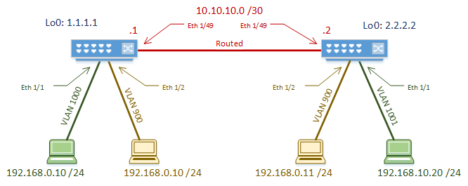
As with the simpler flood and learn lab, we’re going to use a simple two-switch topology. Yes, spine/leaf may be better in the real world, but this is simpler for learning VxLAN.
The routed link between the switches is the underlay. OSPF is used as the underlay routing protocol.
We’re using IPv4, but IPv6 would follow the same principles.
This time, we have two tenants. One tenant has a LAN segment (VNI) that spans the two switches. The other has two VNI’s, which requires routing between. Some of the address space overlaps, so we will see how BGP can keep the tenants separate.
We use MP-BGP in the overlay. Both switches are in AS 65535. Integrated Routing and Bridging (IRB) is used to route between the VNI’s. This also means that we’ll use anycast gateway on both switches.
BUM traffic will be handled by Head End Replication. This is also known as Ingress Replication. This is not as efficient as multicast, but is very simple to configure. Also, we saw multicast used in the flood and learn lab, so we’re trying something different here.
Now that we’re not using multicast, we only need a single loopback interface. This is only used to give the NVE interface an IP, and the BGP source.
Underlay
The underlay configuration is nearly the same as in the previous lab, so I won’t get into too much detail.
The big difference is that there is only a single loopback interface.
As a bonus tip, if you want to use vPC, add a secondary IP to the loopback interface. This IP needs to be the same on the pair of vPC switches.
We won’t be using vPC in this lab, but this is a starting point if you need it.
Overlay
Global Config
We’ll start by enabling features. The two new features here are interface-vlan and nv overlay evpn.
Interface vlan is used to create a virtual interface based on a VLAN. We use this to create the anycast gateway IP for the VNI, and to tie VNI’s to a tenant’s VRF. Don’t worry, it’ll make more sense soon.
Overlay evpn adds the EVPN address family.
Switch-1(config)# feature bgp
Switch-1(config)# feature interface-vlan
Switch-1(config)# feature vn-segment-vlan-based
Switch-1(config)# feature nv overlay
Switch-1(config)# nv overlay evpn
There is a vMAC address on each switch for the Anycast Gateway. This is the same on each switch. Making this the same on each means that any switch can respond as the default gateway.
As shown below, some versions of NXOS need a routing template to be set. This is used to change the way memory is partitioned for routes. This needs to be set in 7.0(3)I5(1) and earlier. Newer versions take care of this transparently.
Switch-1(config)# fabric forwarding anycast-gateway-mac 0000.2222.3333
Switch-1(config)# System routing template-vxlan-scale
The NVE interface is the VTEP. There is only one of these per switch. It uses the loopback interface to get its IP address.
We set BGP as the host-reachability protocol, which enables BGP control plane learning. If this isn’t enabled, then we’re using flood and learn.
The BGP instance is configured mostly as normal. Remember that this is iBGP, so in the real world you need to make sure that you have a full mesh or route reflectors.
We enable the L2VPN EVPN address family, which lets MP-BGP carry MAC addresses.
Extended communities are enabled. This is to support carrying route-target information.
The First Tenant
It’s time to add the first tenant. The configuration here is the same on both switches.
Firstly, we need to create a VRF. This is associated with VNI 900001, making this an L3VNI. The L3VNI defines the tenant within the fabric, and contains L3 routes for the tenant.
A Route Distinguisher is used to keep the VRF unique in the MP-BGP database. Setting the value automatically is the simplest option.
Route Targets are also assigned automatically. Automatic assignment is recommended unless you have a mixed-vendor environment.
Switch-1(config)# vrf context Tenant-1
Switch-1(config-vrf)# vni 900001
Switch-1(config-vrf)# rd auto
Switch-1(config-vrf)# address-family ipv4 unicast
Switch-1(config-vrf-af-ipv4)# route-target both auto
Switch-1(config-vrf-af-ipv4)# route-target both auto evpn
The L3VNI needs an SVI to be created on each switch. SVI’s are based on VLAN, so we need to associate VNI 900001 with VLAN 101 first.
The SVI then needs to be created and associated with the tenant’s VRF. The SVI and VRF represent the tenant’s routing boundary.
The ip forward command is added to the SVI. This command enables routing. Technically, it enables the switch to take the decapsulated VxLAN packet, and forward it to the CPU or Supervisor for handling.
In BGP, we need to add the Tenant’s VRF. Inside this, we use the advertise l2vpn evpn command. This enables advertising EVPN routes (MAC addresses) within the tenant.
Switch-1(config)# vlan 101
Switch-1(config-vlan)# vn-segment 900001

Switch-1(config)# int vlan 101
Switch-1(config-if)# no shutdown
Switch-1(config-if)# vrf member Tenant-1
Warning: Deleted all L3 config on interface Vlan101
Switch-1(config-if)# ip forward

Switch-1(config)# router bgp 65535
Switch-1(config-router)# vrf Tenant-1
Switch-1(config-router-vrf)# address-family ipv4 unicast
Switch-1(config-router-vrf-af)# advertise l2vpn evpn
Now it’s time for the L2VNI’s. These are the more traditional LAN segments.
We start with binding VNI 5000 to VLAN 1000. VNI 5000 then needs to be added to the VTEP. This is also where we enable ARP Suppression, and configure ingress replication. Finally, associate the VNI with the tenant’s L3VNI/VRF to enable IRB.
Each VNI that needs to be routable needs to have an SVI in the tenant’s VRF. This SVI is given the same IP address on each switch, which enables Anycast Gateway.
Switch-1(config)# vlan 1000
Switch-1(config-vlan)# vn-segment 5000

Switch-1(config-if)# interface nve1
Switch-1(config-if-nve)# member vni 5000
Switch-1(config-if-nve-vni)# suppress-arp
Switch-1(config-if-nve-vni)# ingress-replication protocol bgp
Switch-1(config-if-nve-vni)# member vni 900001 associate-vrf

Switch-1(config-vlan)# interface vlan 1000
Switch-1(config-if)# no shutdown
Switch-1(config-if)# vrf member Tenant-1
Warning: Deleted all L3 config on interface Vlan1000
Switch-1(config-if)# ip address 192.168.0.1/24
Switch-1(config-if)# fabric forwarding mode anycast-gateway
Now we need to enable sharing EVPN routes (MAC addresses). This looks a lot like normal BGP configuration.
In EVPN configuration, each L2VNI needs to have an RD and RT’s assigned. This is because they use a MAC-VRF. In the MP-BGP database, L3 routes and L2 MAC addresses are in separate VRF’s. These values are still set to auto in our case, but are different to the L3VNI’s RD’s and RT’s in MP-BGP.
I know that this might sound a bit confusing. Just remember that you need to advertise L3 information into BGP, as well as separate L2 information. Even though all this is part of the same tenant, L2 and L3 addresses are different, and are treated like they’re different address families.
Switch-1(config)# evpn
Switch-1(config-evpn)# vni 5000 l2
Switch-1(config-evpn-evi)# rd auto
Switch-1(config-evpn-evi)# route-target import auto
Switch-1(config-evpn-evi)# route-target export auto
The host ports are configured as normal access ports. This example is only on Switch-1.
Switch-1(configi)# interface eth 1/1
Switch-1(config-if)# switchport
Switch-1(config-if)# switchport access vlan 1000
Switch-1(config-if)# no shutdown
Now let’s add another VNI for this tenant. This is basically the same process that we just went through.
Switch-1(config)# vlan 1001
Switch-1(config-vlan)# vn-segment 5005

Switch-1(config)# interface vlan 1001
Switch-1(config-if)# no shutdown
Switch-1(config-if)# vrf member Tenant-1
Warning: Deleted all L3 config on interface Vlan1001
Switch-1(config-if)# ip address 192.168.10.1/24
Switch-1(config-if)# fabric forwarding mode anycast-gateway

Switch-1(config)# interface nve1
Switch-1(config-if-nve)# member vni 5005
Switch-1(config-if-nve-vni)# suppress-arp
Switch-1(config-if-nve-vni)# ingress-replication protocol bgp

Switch-1(config)# evpn
Switch-1(config-evpn)# vni 5005 l2
Switch-1(config-evpn-evi)# rd auto
Switch-1(config-evpn-evi)# route-target import auto
Switch-1(config-evpn-evi)# route-target export auto
And finally the host port on Switch-2.
! This part only on SW-2
Switch-2(config)# interface ethernet 1/1
Switch-2(config-if)# switchport access vlan 1001
The Second Tenant
Now to repeat the process to add the second tenant. This follows the same basic process:
- Create VRF
- Create L3VNI
- Create L2VNI and anycast gateway
- Add L2VNI to VTEP
- Add L2VNI to EVPN
Switch-1(config)# vrf context Tenant-2
Switch-1(config-vrf)# vni 900002
Switch-1(config-vrf)# rd auto
Switch-1(config-vrf)# address-family ipv4 unicast
Switch-1(config-vrf-af-ipv4)# route-target both auto
Switch-1(config-vrf-af-ipv4)# route-target both auto evpn

Switch-1(config)# vlan 102
Switch-1(config-vlan)# vn-segment 900002

Switch-1(config)# interface vlan 102
Switch-1(config-if)# no shutdown
Switch-1(config-if)# vrf member Tenant-2
Warning: Deleted all L3 config on interface Vlan102
Switch-1(config-if)# ip forward

Switch-1(config)# vlan 900
Switch-1(config-vlan)# vn-segment 6000

Switch-1(config)# interface vlan 900
Switch-1(config-if)# no shutdown
Switch-1(config-if)# vrf member Tenant-2
Warning: Deleted all L3 config on interface Vlan900
Switch-1(config-if)# ip address 192.168.0.1/24
Switch-1(config-if)# fabric forwarding mode anycast-gateway

Switch-1(config)# interface nve1
Switch-1(config-if-nve)# member vni 900002 associate-vrf
Switch-1(config-if-nve)# member vni 6000
Switch-1(config-if-nve-vni)# suppress-arp
Switch-1(config-if-nve-vni)# ingress-replication protocol bgp

Switch-1(config)# evpn
Switch-1(config-evpn)# vni 6000 l2
Switch-1(config-evpn-evi)# rd auto
Switch-1(config-evpn-evi)# route-target import auto
Switch-1(config-evpn-evi)# route-target export auto
And the host ports.
Switch-1(config)# interface ethernet 1/2
Switch-1(config-if)# switchport
Switch-1(config-if)# switchport access vlan 900
Switch-1(config-if)# no shutdown

Switch-2(config)# interface ethernet 1/2
Switch-2(config-if)# switchport
Switch-2(config-if)# switchport access vlan 900
Switch-2(config-if)# no shutdown
Verification
To verify, start by checking that BGP neighbours are forming. This is almost identical to regular BGP.
Remember to check the State/PfxRcd field.
Now, lets look at the NVE peers. This is where we can see the remote VTEPs that have been discovered.
Notice that the LearnType field shows CP, for control plane learning.
Now, see the VNI’s that are associated with the local VTEP.
Look at the Type column. This tells us if this is a layer-2 or layer-3 VNI. If it’s an L2VNI, the associated VLAN comes next. If it’s an L3VNI, the VRF comes next.
L2VNI’s may have an SA flag. This indicates that ARP suppression is enabled.
The Multicast-group column would normally contain the mcast group used for BUM traffic. This is set to UnicastBGP in our case, as we’re using ingress replication.
show vxlan is a simple command to show VLAN to VxLAN (VN-Segment) bindings.
Now, have a look at layer-2 routing information. As MAC addresses are learned, they are added here.
The first entry in the example below is learned through BGP. The second has been learned on the local switch, on interface eth 1/1.
Switch-1# show l2route evpn mac-ip all
Flags -(Rmac):Router MAC (Stt):Static (L):Local (R):Remote (V):vPC link
(Dup):Duplicate (Spl):Split (Rcv):Recv(D):Del Pending (S):Stale (C):Clear
(Ps):Peer Sync (Ro):Re-Originated
Topology    Mac Address    Prod   Flags         Seq No     Host IP         Next-
Hops
----------- -------------- ------ ---------- --------------- ---------------
1000        b4b5.2f7b.182a HMM    --            0          192.168.0.10   Local
This final command is the big one. This is the BGP database.
There are several entries of note here. Routes are grouped by route distinguisher. This represents the tenant’s VRF.
Each of these entries is type-2 or type-3, meaning L2VNI or L3VNI. The important parts though are the MAC and IP addresses, and the next-hop (remote VTEP).
Migrated Comment:
Nexus 9k possible problems
Kristof (unverified) 2018-06-07 18:01
Hi,
Your design works fine, but there is a problem when you change the layer3 interfaces to SVI interfaces. Everything looks fine in ‘sh l2route evpn mac all’ and in BGP, but SVI interfaces do not pass the traffic.
Another issue is when you change the iBGP to eBGP. BGP sessions are up, but no prefixes/mac’s are passed from one end to the other.
Have you met with similar problems? Maybe it is just how cisco implemented in 9k platform.
The lack of prefixes/mac’s between eBGP peers might be due to Your route-targets.
If You are using route-target auto for Your EVPN, the RT will be come ASN:X
With a similar configuration at the remote site, the prefixes will not be imported due to different RT’s.
You can use the “rewrite-evpn-rt-asn” under Your AF “address-family l2vpn evpn”
Thanks, that’s a good tip
Migrated Comment:
Nexus 9k possible problems
Luke Robertson 2018-06-09 18:47
I haven’t seen these problems myself.
For the SVI’s, make sure you are using ‘ip forward’. I think anycast gateway is optional. Try without that, and see if that helps.
Are you talking about using eBGP in the underlay or overlay? I haven’t done it, but I’m fairly sure eBGP is supported in the underlay, but I’m not sure about the overlay.
I attended a session at Cisco Live in Melbourne earlier this year that may help. It’s called “Troubleshooting VxLAN BGP EVPN – BRKDCN-3040”. The recording is here:
https://www.ciscolive.com/global/on-demand-library/?search=vxlan#/session/1507093353793001jMwy
Let me know how you go
I have weird situation when I create a VxLAN network.
I connect ASR1006-X Directly to Spine as a DCI solution connect to remote many different BANK wan.
ON ASR1006 ,I create a interface nve1 and config bgp evpn as control plane to transmit layer 3 VxLAN route information , and create VRF outside interface connecting to remote bank router , that is ok , I CAN ping from remote bank router to inside many sets of nexus 93180YC-EX switch(as many sets leaf,also running bgp evpn)
the problem is coming when I start to config layer2 VxLAN on ASR 1006, I plan let remote bank’s server can layer2 access inside VxLAN server leaf(under nexus 93180 switch), but on ASR 1006, I can’t config layer 2 vni under same interfave nve 1 as vxlan layer3 vni as I configured above.
So I create a new interfave nve2,and config layer 2 vni under new interfave nve2, but from cisco doc, it hasn’t told me ,I can config vxlan layer 2 vni by using bgp as control plan , in fact ,I can’t config bgp under interfave nve2 which I configured layer2 vni, It told me I can’t config bgp and layer 2vni together, I check cisco doc again and again ,there is no sample configuration for bgp and l2 vni, just bgp vxlan layer3, but cisco didn’t tell me you can’t do this.
So I have to change multicast or ingress replication under interfave nve2,
the real problem appear
on inside vxlan network many set leaf swtich(nexus 93180), It has already configured bgp evpn for layer2 and layer3 vni between these nexus 93180 switch ,I can’t modify it,
I tired remove host-reachablility protocol bgp on one set on nexus 93180 leaf, just using multicast or ingress replication to connect asr 1006 layer2 vxlan , It is running ,running is ok
but when I return my configuration back to bgp mode on nexus 93180, layer 2 vxlan ping from asr1006 to 93180 leaf was failed,
I think asr 1006 can’t support bgp evpn and layer 2 vxlan , just only multicast or ingress replication
but on 93180, I can’t config pure multicast or ingress mode connecting to ASR 1006 layer 2 vxlan, because on 93180 I can only create just one interface nve1, I can’t remove bgp configuration under interface nve1 on 93180 switch because there are many set on 93180 leaf in vxlan network,
I totally confused for this situation, luckly customer now don’t have layer 2 vxlan connection for DCI.
but when customer has layer2 vxlan connection from ASR1006 ,how can I do this.
thank you
Jun
anther question :
you said layer2 mac and layer 3 ip routing put into different vrf, you mean:
1 type 2 mac and ip put into mac-vrf
2 type 5 ip prefic put into ip-vRF
what exactly information put into this two vrf table?
is this right, if I don’t config address-family ipv4 unicast neighbor, just bgp evpn address family
cisco create two vrf ,one for mac-vrf,one for layer3-VRF, how to check this two VRF table?
thank you
Jun
Hello, and thank you for creating these series on VXLAN. My question is simple, I hope. How can VXLAN be implemented on a network that only uses the default VRF in the core? Most of the documentation I have read refers to multi-tenants, including part 6 of your series. Any thoughts?
Thank you!
I’m really not sure… I think you need VRF’s for the BGP address families.
Is there a particular reason why you can’t use VRF’s in your environment?
VRF’s were never adopted, or haven’t been actually. Now that the need for extending critical VLAN has come, VRF’s will likely play a critical part. Another question I had that I believe wasn’t covered in part 6 is route learning. If certain VLANs go into their respective VRF’s but other networks remain in the default one, will BGP and OSPF require redistribution?
If you have routes outside of VXLAN EVPN, then yes, you will need to redistribute. This would (by the textbook) be done between an external router and the leaf switches.
However, in practice you can redistribute anywhere. Be careful though. You should try to keep the underlay routing separate from the overlay. So I would suggest (if possible) to use a separate VRF for the underlay, and never redistribute it.
For this particular situation, I opted for MP-BGP and added the subnets in question to a VRF. I peered the VTEPs with BGP with OSPF in the underlay, then redistributed the host routes from BGP into OSPF. This provided east/west and north/south reachability.
Hi all,
I deployed Nexus 9000v(7.0.3.I7.7) but I do not have ping between the hosts connected to different leafs within the same VXLAN. At same time I see an arp record of the remote host. Is there any problem with N9k when ingress replication is in use ? I do not have any multicast configured, only OSPF for underlay and iBGP.
Someone mentioned that problem above:
Nexus 9k possible problems
Kristof (unverified) 2018-06-07 18:01
Hi,
Your design works fine, but there is a problem when you change the layer3 interfaces to SVI interfaces. Everything looks fine in ‘sh l2route evpn mac all’ and in BGP, but SVI interfaces do not pass the traffic.
Another issue is when you change the iBGP to eBGP. BGP sessions are up, but no prefixes/mac’s are passed from one end to the other.
Have you met with similar problems? Maybe it is just how cisco implemented in 9k platform.
Hello.. Have you solved the problem to ping end to end? I’m facing the same problem.
Hi, I posted the following a while back on your you tube post, I know it is a bit long and detailed, but I was rather hoping that some of the inconsistencies In the video and Notes here could be corrected or clarified with a response?
Original post:
Ok, first off great series, but I do have some questions/comments….
So I’ve been looking through this video, and the corresponding notes at:
https://networkdirection.net/articles/routingandswitching/vxlanoverview/vxlanevpnconfiguration/
I’ve gone through both several times, as there was something that was not adding up for me.
You often refer to “the” anycast gateway, leading me to believe there was only one with one
IP at 192.168.0.1, which did not make sense to me as there were two subnets defined for Tenant 1
(T1) 192.168.0.0/24 & 192.168.10.0/24 (more on this later). But when I went through slowly (you
go pretty quick in places), and referenced the notes I do see that there are two anycast gateways
configured; 192.168.0.1 & 192.168.10.1. (In the Video at 10:34Min the anycast-gateway is
192.168.10.1).
However there are still some inconsistencies that are causing me some confusion….
In the Video at 1:08min the T1 host in VLAN 1001 has an IP of 192.168.10.20/24, consistent with
notes. But then at 1:50min,3:05min & 5:13mins, it changes to 192.168.0.20/24 ?
Also in the Video at 1:11min, 3:05min & 5:13 mins the T2 host in VLAN 900 on Switch 2 has an IP
of 192.168.0.20, but in notes it is 192.168.0.11.
Also at 9:17 min in the video, you create vlan 1000 on Switch-2, but the network diagrams
(notes and video) only show a vlan 1001 on switch-2. Using a vlan 1000 on Switch-2 makes
more sense to me as then the T1 host on switch 2 has the 192.168.0.20 IP i.e in the same subnet
as the T1 host on Switch-1. And indeed then they could both have the same IP for the
anycast-gateway. I also see that you create a VLAN 1000 AND and VLAN 1001 on switch-1
So what I am thinking is that we need to add the both L2 VLAN/VNI mappings to each switch VTEP
for each tenant even though each has only local port access to one or the other VLANs.
T1 Switch-1 is in VLAN/VNI 1000/5000, but Switch-1 is also configured with VLAN 1001, I assume
so that VTEP-1 on Switch-1 can be associated with VNI 5005?
So if the T1 Host 192.168.0.10 in VLAN 1000/VNI 5000 wants to send to 192.168.10.20/192.168.0.20
(not sure which is the right address), then the VTEP on switch-1 knows that IP is in VNI 5005 on
VTEP-2 on switch-2, and sends the packet with VNI 5005 in the VxLAN header, VTEP then
decapsulates and sends on VLAN 1001 on switch-2.
But I’m not sure why switch-1 needs to know the VLAN 1001/VNI 5005 mapping as the packet at
switch 1 has no VLAN 1001 tag, all that VTEP-1 needs to know is that it has to send it to
VNI 5005, it is switch-2/VTEP-2 that needs to know the mapping so it can direct it to the
right switch port.
Also In the notes the “show nve vni” for Switch-1 and Switch-2 both only show vni’s 5000
and 900001?
And “show vxlan” only shows bindings for VLAN 101 & 1000 on both switches?
“show l2route evpn mac all” also seems to be incomplete?
hello, dont u use multicast for l2vni transport ?