
Advanced GRE
Previously, we’ve talked about how GRE works, and how to configure it. But this only really covers the basics. In this article, we’ll look at GRE in-depth, covering:
- GRE with IPSec encryption
- Recursive routing, and how to avoid it
- Improving stability and uptime
Encryption
GRE does not have any built-in encryption. This is a problem if we want to tunnel through a public network like the internet.
Fortunately, it’s rather easy to add IPSec encryption to the GRE tunnel. IPSec is configured in transport mode which means that it only encrypts data, it doesn’t use any native IPSec tunnelling functions.
Please note that when we’re talking about IPSec, we talk about phase-1 and phase-2 tunnels. This is part of how IPSec works, not part of GRE.
It’s quite common for NAT to be used. This presents a problem for native IPSec, as IKE (the phase-1 tunnel) detects IP changes (which is what NAT is for) and drops packets, thinking that they’ve been altered. To solve this problem, a feature called NAT-Traversal (NAT-T) was added.
NAT-T is automatically enabled during the phase-1 exchanges if NAT devices are detected. NAT-T adds an additional header to each encrypted packet. Everything is encapsulated in an extra layer of UDP, to trick IKE into thinking that the packet has not been altered.
If you’re tunnelling through a firewall, you will need to open additional ports and protocols to allow the encrypted traffic through:
- IP Protocol 47 – GRE. This is needed if you’re encrypting or not
- IP Protocol 50 – ESP. This is for encryption
- IP Protocol 51 – AH. This is optional, as AH may or may not be used
- UDP/500 – ISAKMP. This allows the phase-1 tunnel to be built
- UDP/4500 – NAT-T. If used, this port needs to be enabled to allow NAT detection and handling
IPSec adds more headers. This means that the maximum payload size is smaller, so it can fit into the MTU size. The size of the headers varies depending on encryption type, whether NAT-T is used (another 8 bytes) and other factors.
You will add anywhere from 56 bytes to 74 bytes of overhead, depending on these factors. The simplest option is to set the MTU to 1400, and the MSS to 1360 for a regular ethernet interface. Of course, this can change if you have jumbo frames.
Configuration
If you’ve configured IPSec before, this should look very familiar.
We start by configuring the IKE policy. This includes the encryption algorithm, the hashing algorithm, and the Diffie-Hellman group.
We also need to configure the authentication method. In our example, we configure this as pre-share, which means we’ll use pre-shared keys.
Finally, we set the pre-shared key, and configure this device to allow connections from 0.0.0.0 (any device).
crypto isakmp policy 10
 encr aes 256
 hash sha256
 authentication pre-share
 group 19

crypto isakmp key SecretPassword12 address 0.0.0.0
Next, the transform-set. This is the IPSec part. The transform set specifies the encryption algorithm and hashing algorithm. We also set transport mode here.
With this, we create a profile and assign the transform-set to the profile.
crypto ipsec transform-set TRANSFORM esp-aes 256 esp-sha384-hmac
 mode transport

crypto ipsec profile TUNNEL
 set transform-set TRANSFORM
And now, assign the profile to the tunnel interface. Not too hard is it?
interface Tunnel0
 ip mtu 1400
 ip tcp adjust-mss 1360
 tunnel protection ipsec profile TUNNEL
Of course, you need to make sure you have the corresponding configuration on the remote device.
Crypto Maps
If you’ve used IPSec before, you may have used crypto-maps. If so, you’ve probably noticed that we’re not using them here. At least not in configuration…
We create profiles, but in the background, the router is dynamically creating crypto-maps for us.
Part of this is creating a crypto socket. This is the socket in software that is open and listening for traffic. This also brings the tunnel up, so we don’t have to manually generate ‘interesting traffic’, like we had to with manual crypto-maps.
You can see the crypto maps that have been generated with:
show crypto map
Keep Alives
IPSec may optionally have keepalives (this is different to GRE keepalives, which we’ll talk about later).
The keepalive is used as part of Dead Peer Detection (DPD). This enables one IPSec peer to detect the failure of another. It is best practice to enable keepalives.
There are two modes that this can be configured in. The first is ‘periodic’. This will send keepalives at regular intervals. This example sends a keepalive message every 10 seconds.
crypto isakmp keepalive 10 periodic
The other option is to configure on-demand keepalives, which are the default option.
In this case, the number of seconds is the maximum time a router will wait without seeing traffic from its neighbour, before sending a keepalive.
These are preferred in situations like DMVPN, as less bandwidth is used.
crypto isakmp keepalive 10 on-demand
Recursive Routing
We need to be careful how we handle routing. Consider this topology:
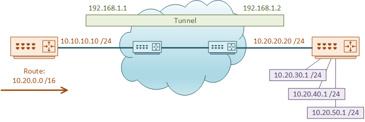
The router on the right has the address 10.20.20.20 as its ‘real’ address. It also has several networks in the 10.20.0.0 /16 range.
The router on the left has a summary route for 10.20.0.0 /16, pointing toward the core. This means it is able to reach the other edge router to build a tunnel.
The tunnel is now built, and the network administrators decide to configure an IGP, such as EIGRP or OSPF. The routers peer over the tunnel, and then they then advertise 10.20.20.0 /24 into the IGP. This is where we run into problems.
The router on the left has now learned 10.20.20.0 /24 dynamically. This goes into the routing table, pushing traffic over the tunnel. This is considered a better path to 10.20.20.20, as it’s a longer match than the /16 it already has.
The left router thinks it can send GRE traffic over the tunnel rather than over the core, which causes the tunnel to collapse. The IGP relationship then drops, causing traffic to be redirected over the core, causing the tunnel to come up again.
The process repeats indefinitely, leaving us with a flapping tunnel.
What we have here is called Recursive Routing. This is where traffic should route over the underlay, but tries to route over the tunnel instead.
There are two main reasons that can cause this:
- The tunnel has a better metric to the network that the ‘real’ IP lives on. This can easily happen with RIP, which uses hop count as the metric
- The tunnel has a longer prefix match to the network that the ‘real’ IP lives on.
There are a few tricks that can help with this. One possibility is to use a different routing protocol for the overlay and the underlay. Perhaps you can use a static route to reach the real IP and a dynamic routing protocol over the tunnel. This would fix the metric problem, but not the longest prefix match problem.
Another option is to use a /32 route to the ‘real’ interface. You can’t get longer than a /32 (with IPv4 anyway), so that goes a long way to solving problem 2.
Mix the two together, and you have a winner!
Tunnel Stability
There’s a few tricks to help stability on your tunnel. We’re going to get a little Cisco-oriented here, but these tricks will likely translate well to other vendors.
Interfaces
Tip #1
Use loopback interfaces
Take a moment to remember how GRE is configured. It needs a source and destination in order to build the tunnel. That means that the tunnel is generally dependant on the underlying interface.
This is an area we can tune. For starters, what if you had more than one path from one router to the other? If we rely on physical interfaces as the source and destination of the tunnel, we may only be using one available path. Instead, we can configure loopback interfaces.
Loopbacks aren’t physical, and therefore, they don’t go down on their own. So if one physical path fails, another may be used. This also leverages ECMP.
Tip #2
Use an interface as the tunnel source
A tunnel source needs to be configured. We have two options for this; Configure an IP as the source, or configure an interface by name. So, what’s the difference? If you use an interface as the source (rather than the IP), the tunnel is tied to the interface. If the interface goes down, so does the tunnel.
If you use an IP as the source this does not happen. So, if there’s a problem with the real interface, the tunnel stays up. This can mean that traffic will continue to flow into the tunnel, even if it should be down. Traffic is now being ‘blackholed’.
Keepalives
Tip #3
Configure keepalives
GRE tunnels are stateless. This means that if a destination IP address is unavailable, the tunnel interface will stay up. This means that traffic will still enter the tunnel, but it will get blackholed.
If you’re using an IGP, then eventually it will notice that the peer is down (thanks to hold timers) and remove it, reroute traffic. But if you’re using static routes, you have a real outage on your hands. Not to mention that convergence is faster if you don’t have to wait for timers to expire.
You can do this with the keepalive command. For example ‘keepalive 10 3‘. This sends a keepalive to the peer every 10 seconds. If 3 in a row are missed, the tunnel’s line protocol is brought down.
Part of the magic of GRE is that the other end does not need any special configuration to listen and respond to the keepalives. The keepalive is double-encapsulated, so the remote peer receives the keepalive, decapsulates it, and is ‘tricked’ into sending the response back to the original source.
However, I do still recommend configuring keepalives on both ends of the tunnel.
There is an important caveat when using GRE + Keepalives + IPSec encryption. Basically, keepalives do not work.
There are two workarounds to this. The first is to use IPSec as a crypto map, rather than applying it to the tunnel. This uses policy-based IPSec, which is outside the scope of this article.
The other workaround is to use another technology to determine if the tunnel is up. This includes timers in an IGP or IP SLA.
References