
DMVPN Configuration
Following on from How DMVPN Works, we’re now going to have a look at how DMVPN is configured.
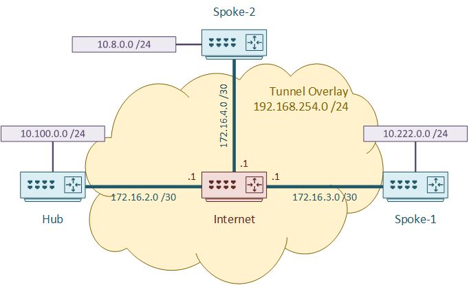
Throughout this article, we’re going to use the topology shown below.
We’re only focusing on DMVPN here. This means that we’re not going to investigate dynamic routing (there will be a future article on this later), or adding IPSec.
We’re going to look at the configuration for each DMVPN phase. You may think that phase 1 is outdated, but it’s especially useful for learning DMVPN in general.
Phase 1, 2, and 3 — Which Should You Use?
Each DMVPN phase builds on the last. Here’s a quick summary of what changes at each stage:
| Phase | Spoke tunnel type | Spoke-to-spoke traffic | Key use case |
|---|---|---|---|
| 1 | Static GRE | Via hub only | Learning DMVPN; small deployments where direct spoke-to-spoke isn’t needed |
| 2 | mGRE | Direct (after NHRP resolution) | Spoke-to-spoke required; routing must not summarise at the hub |
| 3 | mGRE + NHRP shortcuts | Direct via shortcut routes | Spoke-to-spoke required; hub summarisation allowed |
The most important distinction between Phase 2 and Phase 3 is how they interact with routing:
- Phase 2 requires that the hub does not summarise spoke routes. If the hub advertises a summary, a spoke will always route via the hub even if a direct path exists — because the summary matches and the spoke has no more-specific route. Phase 2 works well with EIGRP but requires careful design with OSPF.
- Phase 3 removes this restriction. The hub can advertise a summary, and when a spoke needs to reach another spoke, NHRP installs a more-specific shortcut route that overrides the summary. This makes Phase 3 easier to design and scale.
For most new deployments, Phase 3 is the right choice.
Phase 1
Hub Router
We’ll start by configuring tunnel 0 on the hub router. There are several parts which will be familiar from when you configured a GRE tunnel.
This includes a tunnel IP address, the MTU/MSS (to adjust for the GRE headers), and the tunnel source IP.
The source IP is the NBMA Address of the tunnel, and the Tunnel IP is the logical address.
interface Tunnel0
 ip address 192.168.254.2 255.255.255.0
 ip mtu 1476
 ip tcp adjust-mss 1436
 tunnel source 172.16.2.2

 ip nhrp authentication NHRPKEY
 ip nhrp network-id 1
 tunnel mode gre multipoint

 tunnel key 11
Notice that there is no tunnel destination address? That’s because the destinations are added dynamically, through the NHRP registration process.
There are two commands relating to NHRP. First, we (optionally) set authentication. This is a cleartext key that is sent with NHRP packets.
Next, we set the NHRP Network ID. This is also known as the NHRP Domain. This is conceptually similar to an OSPF process ID.
It’s possible to have NHRP enabled on more than one interface on a router. Perhaps for another DMVPN network, or some other use. The ID tells the router if the interfaces are in the same domain or not.
This value is completely local to the router. It is not sent to any other router, so you can basically set this to whatever you want. It is recommended to keep this value the same across all your routers, to make it easier to troubleshoot.
Finally, we can set the tunnel mode to GRE multipoint. This enables more than one spoke router to connect to the tunnel.
The tunnel key is an optional value that we can use for more authentication. The tunnel key, if set, is in the GRE header. It must match for the tunnel to form.
Spoke Routers
The spoke routers use a similar configuration to the hub. The configuration for Spoke-1 is shown below.
Notice that there is a tunnel destination this time? This is the NBMA address of the hub router.
Also, notice that there is no command to set the tunnel type? That’s because, in Phase-1, spokes use regular GRE tunnels, not mGRE.
interface Tunnel0
 ip address 192.168.254.3 255.255.255.0
 ip mtu 1476
 ip tcp adjust-mss 1436
 tunnel source 172.16.3.2
 tunnel destination 172.16.2.2
 ip nhrp authentication NHRPKEY
 ip nhrp network-id 1
 tunnel key 11

 ip nhrp nhs 192.168.254.2
 ip nhrp map 192.168.254.2 172.16.2.2
The NHS is the Next Hop Server. This is the hub router. This needs to be statically configured. Notice that we use the logical tunnel address here.
The spoke won’t know where to send encapsulated packets yet, so we need to configure a mapping between the tunnel address and the NBMA address.
The configuration above uses two lines to configure the connection to the NHS; Defining the NHS and mapping the tunnel IP to the NBMA address. Later on we’ll add a third command to configure multicast.
Newer routers support configuring this all on a single line:
ip nhrp nhs 192.168.254.2 nbma 172.16.2.2 multicast
Spoke-2 will be configured in almost the exact same way, so I won’t include all the details here. See the lab if you want to see it in action.
Verification
The simplest verification is to ping from one end of the tunnel to the other:
Spoke-1#ping 192.168.254.3
Type escape sequence to abort.
Sending 5, 100-byte ICMP Echos to 192.168.254.3, timeout is 2 seconds:
!!!!!
Success rate is 100 percent (5/5), round-trip min/avg/max = 1/1/1 ms
You can also use show dmvpn to get more detail. On the hub router, we see the spokes listed as dynamic entries (see the attrib column).
You may find that nothing shows up here initially. If not, run a ping to force the spoke to register with the hub.
Hub#show dmvpn
Interface: Tunnel0, IPv4 NHRP Details
Type:Hub, NHRP Peers:2,
# Ent Peer NBMA Addr  Peer Tunnel Add State UpDn Tm  Attrb
----- --------------- --------------- ----- -------- -----
    1      172.16.3.2   192.168.254.3    UP 00:18:03     D
    1      172.16.4.2   192.168.254.4    UP 00:18:02     D
On the spoke side, the tunnel appears as static.
Spoke-1#show dmvpn
Interface: Tunnel0, IPv4 NHRP Details
Type:Spoke, NHRP Peers:1,
# Ent  Peer NBMA Addr Peer Tunnel Add State  UpDn Tm Attrb
----- --------------- --------------- ----- -------- -----
    1      172.16.2.2   192.168.254.2    UP 00:18:31     S
Use show ip nhrp to get NHRP information. The hub has a timer that will clear out unused entries after a while. Spokes will not have this, as they are static.
Hub#show ip nhrp
192.168.254.3/32 via 192.168.254.3
   Tunnel0 created 00:19:01, expire 01:40:58
   Type: dynamic, Flags: unique registered nhop
   NBMA address: 172.16.3.2
192.168.254.4/32 via 192.168.254.4
   Tunnel0 created 00:19:00, expire 01:40:59
   Type: dynamic, Flags: unique registered nhop
   NBMA address: 172.16.4.2
And finally, as traceroute shows that spoke-to-spoke traffic works, but it needs to flow through the hub router.
Spoke-1#traceroute 192.168.254.4 numeric
Type escape sequence to abort.
Tracing the route to 192.168.254.4
VRF info: (vrf in name/id, vrf out name/id)
1 192.168.254.2 5 msec 9 msec 5 msec
2 192.168.254.4 9 msec * 8 msec
Phase 2
The primary difference in Phase-2 is the ability for direct spoke-to-spoke communication. This is enabled by replacing the static GRE tunnel on the spoke with an mGRE tunnel.
There are no differences on the hub, so we’re going to skip straight to the spoke routers.
Spoke Configuration
We’re going to use this to build on the configuration in Phase-1, rather than starting from scratch.
! Spoke-1 Router
interface Tunnel0
 no tunnel destination 172.16.2.2
 tunnel mode gre multipoint
 ip nhrp map multicast 172.16.2.2
The first two commands are what Phase-2 is really about. Static GRE is out, and mGRE is in. This is the key. This is how spokes are able to communicate directly.
The only other thing is to add multicast information. Why do we need to do this now? Think about GRE for a moment. GRE headers include two critical pieces of information; The source IP address and the destination IP address.
Multicast addresses can’t be used as the destination address in an NBMA network. Multicast will still work, but NHRP will need to get involved.
Back when we had a static tunnel on the spoke router, this was easy. Just send multicast packets to the NHS (hub router) and let it manage it from there.
But now we’re using mGRE, which has no static destination. So, the solution is to manually map multicast to the NHS.
Verification
A spoke will now see another spoke as a dynamic DMVPN entry:
Spoke-1#show dmvpn
Interface: Tunnel0, IPv4 NHRP Details
Type:Spoke, NHRP Peers:2,
# Ent  Peer NBMA Addr Peer Tunnel Add State  UpDn Tm Attrb
----- --------------- --------------- ----- -------- -----
    1      172.16.2.2   192.168.254.2    UP 00:04:03     S
    1      172.16.4.2   192.168.254.4    UP 00:01:25     D
Same is true here:
Spoke-1#show ip nhrp
192.168.254.2/32 via 192.168.254.2
   Tunnel0 created 00:05:11, never expire
   Type: static, Flags: used
   NBMA address: 172.16.2.2
192.168.254.4/32 via 192.168.254.4
   Tunnel0 created 00:02:31, expire 01:57:27
   Type: dynamic, Flags: router used nhop
   NBMA address: 172.16.4.2
If we run a traceroute, the first pass will go through the hub, just as Phase-1 did. Shortly later the NHRP redirect process will complete, and a second traceroute will show traffic going straight to the remote spoke.
Spoke-1#traceroute 192.168.254.4 numeric
Type escape sequence to abort.
Tracing the route to 192.168.254.4
VRF info: (vrf in name/id, vrf out name/id)
  1 192.168.254.2 8 msec 9 msec 20 msec
  2 192.168.254.4 4 msec * 4 msec
Spoke-1#traceroute 192.168.254.4 numeric
Type escape sequence to abort.
Tracing the route to 192.168.254.4
VRF info: (vrf in name/id, vrf out name/id)
  1 192.168.254.4 5 msec * 6 msec
Phase 3
Phase-3 adds the ability to simplify over the DMVPN. There are two parts to this; NHRP redirects on the hub, and shortcut routes on the spokes.
Hub Router
The changes to the hub router are really quite simple. One line enables NHRP redirects:
interface Tunnel0
 ip nhrp redirect
This enables the hub to inform a spoke of a better path if one exists.
Spoke Configuration
The spokes also have very simple configuration:
interface Tunnel0
 ip nhrp shortcut
The shortcut command allows the spoke to accept the redirect message from the hub, and install the shortcut route.
Routing Table
To see how this affects the routing table, we’ve added in some static routes. We would normally use dynamic routing, but static is simpler for the example.
To start with, we can see the summary route (10.0.0.0 /8) pointing to the hub:
Spoke-1#show ip route
Gateway of last resort is 172.16.3.1 to network 0.0.0.0

S*    0.0.0.0/0 [1/0] via 172.16.3.1
      10.0.0.0/8 is variably subnetted, 3 subnets, 3 masks
S        10.0.0.0/8 [1/0] via 192.168.254.2
C        10.222.0.0/24 is directly connected, Loopback0
L        10.222.0.1/32 is directly connected, Loopback0
      172.16.0.0/16 is variably subnetted, 2 subnets, 2 masks
C        172.16.3.0/30 is directly connected, GigabitEthernet0/1
L        172.16.3.2/32 is directly connected, GigabitEthernet0/1
      192.168.254.0/24 is variably subnetted, 2 subnets, 2 masks
C        192.168.254.0/24 is directly connected, Tunnel0
L        192.168.254.3/32 is directly connected, Tunnel0
Next, we’ll generate some traffic between the spokes:
Spoke-1#ping 10.8.0.1
Type escape sequence to abort.
Sending 5, 100-byte ICMP Echos to 10.8.0.1, timeout is 2 seconds:
!!!!!
Success rate is 100 percent (5/5), round-trip min/avg/max = 6/15/32 ms
Now the interesting part. Let’s look at the route table again:
Spoke-1#show ip route
Gateway of last resort is 172.16.3.1 to network 0.0.0.0

S*    0.0.0.0/0 [1/0] via 172.16.3.1
      10.0.0.0/8 is variably subnetted, 4 subnets, 3 masks
S        10.0.0.0/8 [1/0] via 192.168.254.2
H        10.8.0.0/24 [250/255] via 192.168.254.4, 00:00:06, Tunnel0
C        10.222.0.0/24 is directly connected, Loopback0
L        10.222.0.1/32 is directly connected, Loopback0
      172.16.0.0/16 is variably subnetted, 2 subnets, 2 masks
C        172.16.3.0/30 is directly connected, GigabitEthernet0/1
L        172.16.3.2/32 is directly connected, GigabitEthernet0/1
      192.168.254.0/24 is variably subnetted, 3 subnets, 2 masks
C        192.168.254.0/24 is directly connected, Tunnel0
L        192.168.254.3/32 is directly connected, Tunnel0
H        192.168.254.4/32 is directly connected, 00:00:06, Tunnel0
See how there are two entries marked with an H code? These are the NHRP shortcut routes. That’s the magic of phase 3!
These entries also show up as shortcuts in the NHRP table.
Spoke-1#show ip nhrp shortcut
10.8.0.0/24 via 192.168.254.4
   Tunnel0 created 00:19:11, expire 01:40:47
   Type: dynamic, Flags: router used rib
   NBMA address: 172.16.4.2
192.168.254.4/32 via 192.168.254.4
   Tunnel0 created 00:19:11, expire 01:40:47
   Type: dynamic, Flags: router nhop rib
   NBMA address: 172.16.4.2
Unique Registration
We’ve discussed before that DMVPN can support dynamic IP’s on the spoke end.
There is a catch though. By default, each tunnel IP must be mapped to a unique NBMA address. So, if the NBMA address changes, the hub will suddenly see a new mapping, which is not unique.
To work around this, which is indeed a Cisco recommended best practice, we configure the router to not enforce unique mappings:
ip nhrp registration no-unique
Troubleshooting
Tunnel not forming / spokes not registering
Start with show dmvpn on the hub. If no spokes appear, NHRP registration is failing.
Hub#show dmvpn
Interface: Tunnel0, IPv4 NHRP Details
Type:Hub, NHRP Peers:0,
Check these values on both hub and spoke — they must all match:
! Verify tunnel key matches on both ends
Hub#show interfaces tunnel 0 | include Tunnel key
  Tunnel key 0x0000000b (11)

! Verify tunnel source interface is up
Spoke-1#show interfaces tunnel 0 | include Tunnel source
  Tunnel source 172.16.3.2 (GigabitEthernet0/1), destination 172.16.2.2
A mismatched tunnel key is a common cause — if the hub uses tunnel key 11 and a spoke uses tunnel key 12, the tunnel appears to form but NHRP packets are silently dropped. Also confirm the spoke’s tunnel destination points to the hub’s correct NBMA address.
Spoke-to-spoke traffic always going via hub (Phase 2/3)
The first packet in Phase 2/3 always goes via the hub — this is expected. The problem is if subsequent packets never go direct.
Confirm the spoke is using mGRE and not static GRE:
Spoke-1#show interfaces tunnel 0 | include Tunnel protocol
  Tunnel protocol/transport multi-GRE/IP
If it shows GRE/IP instead of multi-GRE/IP, the spoke is still in Phase 1 mode. Apply tunnel mode gre multipoint to the tunnel interface. Also confirm the multicast map is configured:
Spoke-1#show ip nhrp multicast
Tunnel0
  Multicast NBMA: 172.16.2.2 (NHS)
If the multicast NBMA is missing, add ip nhrp map multicast 172.16.2.2 to the spoke tunnel interface.
Phase 3 shortcuts not installing
Verify the hub has ip nhrp redirect and the spoke has ip nhrp shortcut:
Hub#show running-config interface tunnel 0 | include nhrp redirect
 ip nhrp redirect

Spoke-1#show running-config interface tunnel 0 | include nhrp shortcut
 ip nhrp shortcut
After generating traffic between spokes, check whether shortcuts are installing:
Spoke-1#show ip nhrp shortcut
10.8.0.0/24 via 192.168.254.4
   Tunnel0 created 00:00:12, expire 01:59:45
   Type: dynamic, Flags: router used rib
   NBMA address: 172.16.4.2
If nothing appears, check that routing is correctly configured — the spoke needs a route to the remote spoke’s LAN before NHRP can install a shortcut.
Intermittent drops / large packets failing
DMVPN adds GRE overhead to every packet. If ip mtu 1476 and ip tcp adjust-mss 1436 are missing from the tunnel interface, large frames will be dropped or fragmented.
Spoke-1#show interfaces tunnel 0 | include MTU
  MTU 17916 bytes, BW 100 Kbit/sec, DLY 50000 usec,
An MTU of 17916 means the tunnel-specific MTU hasn’t been set. Configure it on the tunnel interface:
interface Tunnel0
 ip mtu 1476
 ip tcp adjust-mss 1436
Test with a large df-bit ping to confirm:
Spoke-1#ping 192.168.254.2 size 1476 df-bit
Hi,
Thank you for the very helpful post. I have already dabbled in some DMVPN labs, including the dual hub kind, notwithstanding, your post certainly afforded me valuable greater insight.
Q: Since under Phase 2, based on the 2nd trace route showing a single hop, it seems the spokes already bypass the hub, meaning the source spoke gets to remote spoke optimally, is the Phase 3 configuration then become superfluous? I am missing something.
DMVPN without multiple VRFs, MPLS and dynamic routing linking into the LAN does not complete the picture. Kindly consider a blog on that.
Thank you again for a most excellent work.
Phase three changes the way routing works. It now can add shortcut routes into the routing table dynamically. I am considering creating a video explaining this.
Phase 3 also has some extra features which I didn’t get into here. For example, it adds options for hierarchical deployment of hubs. This would normally only matter in a large deployment.
VRF+MPLS is a good option if you want multi-tenancy on your DMVPN, but not everyone does. In fact it’s not even the only multitenancy options (multi-tunnel in phase 3 for example).
I recommend watching some of the DMVPN videos on Cisco Live on demand, as they describe these options in detail.